-
CM5-Tiny: Difference between revisions
| Line 21: | Line 21: | ||
|- | |- | ||
| '''Key Features''' || | | '''Key Features''' || | ||
* ''' | * '''Compatible with all Raspberry Pi CM5 core boards ''', connector model DF40HC3.0 | ||
* ''' | * '''USB 3.0 Type-C ''': Reversible insertion is not supported; one side is USB 3.0, the other side is USB 2.0. Please pay attention to the insertion orientation. | ||
* ''' | * '''USB 2.0 OTG ''': Supports eMMC/TF card system programming and can be configured as a USB network card under OpenWrt. | ||
* ''' | * '''USB 2.0 connector ''': 1.25mm-4Pin, can be used for 4G module expansion. | ||
* ''' | * '''PCIe slot ''': 0.5mm-16Pin; can be used to expand peripherals such as WiFi/SSD/USB/2.5G network/AI/TPU. | ||
* ''' | * '''RTC Real-Time Clock ''': 1.25mm - 2Pin | ||
* ''' | |||
* ''' | * '''PWM Fan Interface ''': 1.0mm - 4Pin | ||
* ''' | |||
* ''' | * '''Micro HDMI ''': Supports up to 4K video output | ||
* ''' | |||
* ''' | * '''0.5mm 22-pin CSI/DSI Combination FPC Port ''': For connecting a display or camera | ||
* ''' | |||
* ''' | * '''GPIO Expansion Header ''': 0.5mm - 20Pin | ||
* '''TF Card Slot ''': For booting the system on CM5 core boards without eMMC only. Can be directly programmed via USB OTG port without removing the board and using a USB card reader. | |||
* '''BOOT Pin Header ''': 2.54mm - 2Pin, BOOT button. Press and hold while powering on to enter BOOT mode (Rev1.3 and Rev1.4). Used for programming the eMMC core board. | |||
* ''' Power Supply ''': 5V 3A, USB-C powered, can be powered via USB-C OTG or USB 3.0-C | |||
* '''3 Status Indicators ''': Power Indicator, CM5 Power Indicator, Run Indicator | |||
|- | |- | ||
| '''Technical Specification''' || | | '''Technical Specification''' || | ||
Revision as of 17:44, 6 July 2026


Overview
The CM5_Tiny is a small expansion board designed specifically for the Raspberry Pi CM5 core board. It features standard interfaces including MicroHDMI/RTC/CAM/DISP/Fan/USB 3.0, with the HDMI port supporting 4K output, as well as a power button, a 1.25mm 4P USB port, and a 16Pin PCIe slot. It also has a dedicated USB 2.0 OTG port, which can be used to program the system to an eMMC/TF card and can be configured as a USB network adapter under OpenWrt. With OpenWrt, the CM5_Tiny can connect to a router via WiFi as a WLAN, and connect to a PC via USB OTG as a LAN.
With 4G LTE, the CM5_Tiny can connect to a PC via 4G under OpenWrt, using either WiFi or USB OTG on the CM5 core board itself as a LAN.
Features
| For use with |
Raspberry Pi Compute Module 5 (CM5) |
| Key Features |
|
| Technical Specification |
Power supply:
Video: 2 x full-size HDMI 2.0 connectors
|
| Important Notes |
For optimal performance, please use the official Raspberry Pi 27W USB-C Power Supply or an alternative power supply capable of delivering 5.1V at 5A. An incompatible power supply with a lower output voltage may fail to power on the system.. |
User Manual
- The hardware design refers to the official design, please refer to: https://datasheets.raspberrypi.com/cm5/cm5io-datasheet.pdf
- Hardware Installation: X1501 Hardware, please click the left link to view it, it's very important!
- How to make it work: X1501 Software, please click the left link to view it, it's very important!
- https://smarthomecircle.com/how-to-install-os-on-raspberry-pi-compute-module-5-emmc-storage
- how to flash os into cm5 emmc, Refer to the following:
- https://smarthomecircle.com/how-to-install-os-on-raspberry-pi-compute-module-5-emmc-storage
- https://www.youtube.com/watch?v=SWv-WYlHJWQ
- Configuration steps for using an external antenna:
https://www.raspberrypi.com/documentation/computers/compute-module.html#antenna
Packing List
CM5 carrier board Kit
- X1501 V1.0 CM5 carrier board x1
- M.2-A1 extension board x2 (to fix M.2 2230 and 2242 SSDs)
- 2.54mm jumer cap x2
- M2*3 screw x 6

Matching Case
According to user feedback, we have designed a metal case X1500-C1 / X15-C1 specifically for X1500 / X1501 IO boards. X15-C1 and X1500-C1 have different sizes, different appearances, and the same usage.
Here is a detailed comparison:
| Model | Compatible with | compatibility | Cooler / Heatsink |
|---|---|---|---|
| X15-C1 V1.0 | Raspberry Pi CM5 | X1500/X1501/other low-profile expansion HATs | X15-F1 |
| X1500-C1 | Raspberry Pi CM5 | X1500/X1501 | C519 |
Please note: The metal case will shield the wifi signal, so please use Ethernet when you use this case
-
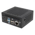 X15-C1
 -
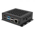 X1500-C1
 -
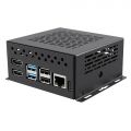 X1500-C2


Installation Tips for C519 & X1500/X1501
Since both the C519 heatsink and PCB holes are threaded, proper alignment and minimal spacing are crucial during assembly. Carefully align the C519 with the PCB mounting holes, press down firmly until the heatsink touches the PCB, then tighten the screws.


Video Guide
Installation Video: https://youtu.be/H1vgT2lrJQI
FAQ
Q. Why can't X1500/X1501 boot up?
A: First, please confirm that your Raspberry Pi CM5 module is working properly. You can refer to online guides for instructions on how to verify that the CM5 is functioning correctly.
Due to PD power compatibility issues, some PD power supplies may cause X1500/X1501 to fail to boot up. Please replace the official Raspberry Pi 5 power supply or Geekworm PSU20 power supply.
Q: Is X1500/X1501 compatible with POE+ Hat?
A: X1500/X1501 is compatible with X15-POE1.
We tested the [Official Raspberry Pi4 POE+ Hat] and it can be compatible, but the cooling fan did not work, probably due to the OS configuration. If you are interested, you can also test it and look forward to your sharing of your suggestions.


Q: Is the X1501 2.5G ethernet port on the PICe bus along with the M.2 devices?
A: No, the X1501 2.5G Ethernet port is connected via the USB 3.0 interface.
Q: How to configure for an external antenna?
A: When using an external antenna, you need to configure the device accordingly. Please follow the official Raspberry Pi documentation for the configuration steps: https://www.raspberrypi.com/documentation/computers/compute-module.html#antenna

Q: What driver do I need for the X1501 2.5GbE Ethernet on OpenWrt?
A: No additional driver is required. Once the X1501 is installed on the CM5, it works just like a Raspberry Pi 5, and the 2.5GbE Ethernet can be used directly under OpenWrt.
Q. Is X1500/X1501 compatible with X1209 UPS?
A: Yes, the X1500/X1501 is compatible with the X1209 UPS. However, the power button on the X1209 only supports press-to-power-on and triple-press for a forced shutdown. Based on customer testing, the clearance between the bottom of the X1209 board and the top surface of the mounted CM5 is approximately 9.45mm (excluding the height of the processor and other chips). Due to this limited space, the C519 heatsink is not compatible with this configuration.At present, there is no suitable heatsink solution available for this specific setup.
