-
CM5-Tiny


Important Notes
- The USB 3.0 Type-C port does not support reversible insertion; confirm orientation before plugging in.
- CM5 core boards with eMMC only boot from eMMC; the onboard TF card slot is invalid for these versions.
- The power on/off button is natively supported by Raspberry Pi OS and Ubuntu; not supported by default in OpenWrt.
- PCIe expansion modules (WiFi7/SSD/TPU/AI) require a dedicated same-direction PCIe FPC cable.
Overview
The CM5_Tiny is a small expansion board designed specifically for the Raspberry Pi CM5 core board. It features standard interfaces including MicroHDMI/RTC/CAM/DISP/Fan/USB 3.0, with the HDMI port supporting 4K output, as well as a power button, a 1.25mm 4P USB port, and a 16Pin PCIe slot. It also has a dedicated USB 2.0 OTG port, which can be used to program the system to an eMMC/TF card and can be configured as a USB network adapter under OpenWrt. With OpenWrt, the CM5_Tiny can connect to a router via WiFi as a WLAN, and connect to a PC via USB OTG as a LAN.
With 4G LTE, the CM5_Tiny can connect to a PC via 4G under OpenWrt, using either WiFi or USB OTG on the CM5 core board itself as a LAN.
Features
| For use with |
Raspberry Pi Compute Module 5 (CM5), connector model DF40HC3.0 |
| Key Features |
|
| Technical Specification |
Input Power:
Video: 1× Micro HDMI, up to 4K resolution Mechanical:
PCB & Compliance
|
User Manual
OS Flashing
- Official flashing operation guide: S001 Flash OS
System Guides
- Raspberry Pi OS usage and functionality test: Raspberry Pi OS Guide
- OpenWrt system configuration and usage: OpenWrt Guide
Optional General Reference
System Programming
1. Core Board Version Differentiation
- - No eMMC Version: Supports TF card booting. The system can be programmed via a card reader or via the onboard OTG interface without removing the card.
- - With eMMC Version: Only supports eMMC booting. The onboard TF card is invalid. The system must be programmed via USB OTG.
2. USB OTG Programming Steps
Press and hold the onboard BOOT button. Connect the OTG port to the computer using a USB-C cable and power on. Release the button after the computer recognizes the BCM2712 device to begin system programming. Power on again after programming is complete.
Packing List
- CM5_Tiny expansion board × 1
- CNC aluminum alloy casing A × 1
- Fixing screws × 4
Note: Raspberry Pi CM5 core board, antenna, fan, and expansion modules are not included.

GPIO Adapter
This GPIO adapter is specifically designed for the CM5 Tiny with its onboard 0.5mm 22Pin FPC GPIO. It is not compatible with the standard 40Pin Raspberry Pi GPIO or other carrier boards.It converts the onboard 0.5mm 22Pin FPC GPIO connector to a standard 2.54mm 2×10 male header, breaking out UART, SPI, PWM, 3.3V and GND signals via 20 active pins. Includes matching 22Pin FPC flexible cable. Works with common Dupont wires, sensors and relay modules — eliminates messy flying wires and simplifies embedded prototyping.
-
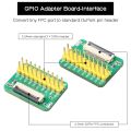 GPIO Adapter
 -
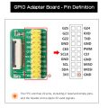 GPIO Adapter
 -
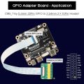 GPIO Adapter
 -
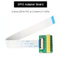 GPIO Adapter


Matching Case
- The CNC aluminum alloy casing is compact and exquisite, and provides heat dissipation for the CM5 core board.
- A reserved antenna interface is provided: the WiFi CM5 core requires an external antenna (the metal casing will block the WiFi signal).
- It is only compatible with single-board units; PCIe expansion modules cannot be stacked internally.
