X650


Contents
Overview
X650 shield is a member of the PiKVM[1] family. It is a Raspberry Pi CM4-based KVM-over-IP remote management PCI Express card that can be easily inserted into 1U and 2U form factors for PC, Sun and Mac platforms. It adds remote, unblocked, BIOS-level access and control to any server. Accessed from any web browser, it provides anytime, anywhere KVM access with security, stability and speed.
This IP KVM PCI card X650 offers KVM control from the BIOS-level onward. Reboot, monitor the entire boot process, and interact with your connected system easily, while the integrated remote ATX power control allows you to switch the machine on/off, reset it, and monitor power & storage LED activity remotely.
The x650 itself has a built-in Toshiba TC358743 chip, so it no longer needs the X630 for the HDMI to CSI function.
The X650 is also equipped with half-height and standard-height bracket, both mini and standard desktop hostsworkable.
Want to know more information for pikvm, please refer to https://pikvm.org/
Features
- Only Compatible with the Raspberry Pi Compute Module 4 and Compatible with all variants, and full Compatible with PiKVM OS (Raspberry Pi-based KVM over IP)
- PCI style, installs justs like any PCI card into a tower / desktop PC
- Supports video and audio.
- Low profile and standard profile bracket Inside-both Mini and standard desktop host workable
- HDMI Full HD capture based on the Toshiba TC358743 chip,supports HDMI input resolutions up to 1920x1080
- OTG Keyboard & mouse; Mass Storage Drive emulation
- Hardware Real Time Clock (RTC) with CR1220 coin battery socket
- Gigabit Ethernet socket supporting Power over Ethernet (POE) expansion, reserve the 4-PIN POE Pin.(Need extra PoE module)
- Equipped with cooling fan that allows the heat from your CM4 to dissipate
How to Power
- Power Input: 5.1Vdc +/-5% , ≥3A (Power via USB Type-C PWR port of X650)
- Use splitter to get POE power supply, refer to PoE splitter.

About POE Splitter, refer to PD3005G-3A
How to Cool
- X650 equipped with an active cooling fan board (X680-A1) that can cool your Raspberry Pi CM4, and X680-A1 is included in the Packing List;
- In fact, if you don't like fans, you can try C235, which can fully meet the cooling needs of CM4, but C235 is NOT included in the Packing List;
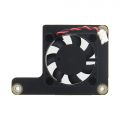
X680-A1


User Manual
First you need to make sure your hardware connections are correct, please refer to the video and diagram below
Installation Video
X650: https://youtu.be/2nKzQlkTXF8
OS download and install
1. Firstly, need prepair a micro sd card, a minimum 16 Gb class 10 memory card is recommended.
2. Download an appropriate OS image for the PiKVM, the url link is https://pikvm.org/download/ or click this one to download it. (Please use the V3 HAT OS)
3. Flash OS image into Micro SD card
1) How to installing the Operating System (CM4 without eMMC)
Refer to Official installation tutorial
2) How to flash OS onto the eMMC of CM4? (CM4 with eMMC)
a. Short nBOOT&GND, refer to the picture below.

b. Connect Type-C OTG to your computer
c. Power the X650 via PWR Type-C with your 5V Power adaper
d. Then rerfer to this tutorial to flash pikvm OS
e. Remove the jumper of nBOOT&GND after flashing is complete, then restart your device;
Packing List
- 1 x X650 V1.3 Expansion Board
- 1 x X680-A1 V1.0 cooling fan Adapter board
- 1 x Colorful ATX Control Cable (Cable Length: 47cm / 18.50 inch)
- 1 x Mini HDMI to HDMI Cable (Length: 50cm/19.69)
- 1 x USB-A to USB-C OTG Cable (Length: 50cm/19.69)
- 1 x Standard height PCIe Add-in Card I/O Bracket
- 1 x Low height PCIe Add-in Card I/O Bracket
- 1 x Screws Pack
FAQ
- First of all, we recommend you to get more FAQ information on the official website: official FAQ, or check the following FAQ;
- You can post a issue ticket at Geekworm forum or email to us (support@geekworm.com) and attached your installation pictures or videos to get some help.
- Blog sharing for reference: https://www.andysblog.de/kvm-over-ip-pikvm-als-bausatz
Why is the X650 not working?
A:1. First you need to make sure your physical connection is correct, or you can email us at support@geekworm.com to confirm your physical connection;
2. Make sure to use the right pikvm OS.


How to switch to root user?
A: run the following command:
su root
Then type the password, the default password is 'root' also.
Does the x650 support audio?
A: Yes. Refer to Enable pikvm hdmi audio
Does the x650 support OLED display?
A: Yes.
Please connect the OLED shield as shown below (But we actually think OLED displays are pointless):

Then run the following command to enable oled display
rw
systemctl enable --now kvmd-oled
ro
About OLED shield, refer to OLED
How to enable RTC?
A: Firstly, insert the C1220 button battery. run the following command:
rw
sudo nano /boot/config.txt
#Then change the line: dtoverlay=i2c-rtc,pcf8563 to dtoverlay=i2c-rtc,ds1307

#Test RTC
#Display the current time of the Raspberry Pi
date
#Write the time of Raspberry Pi to DS1307
sudo hwclock -w

#Read the time of DS1307
sudo hwclock -r
ro
Does the X650 support PoE power? How to enable PoE Power?
A: The X650 reserve the POE port, but need to use with customized POE module to support PoE power, and the customized POE module still not release now. And the X650 does not support the Raspberry Pi official PoE module. Recommend to use PiKVM-A8 kit, if you need PoE power.
References
- ↑ PiKVM © belongs to https://pikvm.org
Enable comment auto-refresher
Anonymous user #4
Permalink |
Anonymous user #4
Permalink |
Anonymous user #4
Permalink |
Anonymous user #3
Permalink |
Lisa
Anonymous user #2
Permalink |
Walker
Anonymous user #1
Permalink |
Harry