UPS Scap 5V5A


Safety Instructions & Warnings
① Short-circuiting the positive and negative terminals of the capacitors is strictly prohibited. Damage caused by a short circuit is not covered under warranty.
② Before storing, please press and hold the discharge button to discharge the capacitors.
③ Before disassembling or assembling modules, please turn off the main power switch.
Overview
The UPS_Scap_5V5A is a supercapacitor-based UPS power module designed specifically for the Raspberry Pi 5. It supports either a 12V PD input or a wide-range 9–24V input (use one or the other), and offers three output options: PD USB-C, USB-A, and pins, with a total output of up to 5V 5A. The USB-C port supports the 5V 5A PD protocol required by the Raspberry Pi 5.
The 100F supercapacitor provides ample power for extended battery life. It features a main power switch and bleed circuitry, and can be mounted on the bottom of the Raspberry Pi for power via header pins or a USB-C to USB-C connector. A power monitoring circuitry allows for reading the supercapacitor's voltage and charging/discharging current via an I2C interface to estimate battery life. A compatible USB-C adapter allows for direct stacking on the bottom of the Raspberry Pi 5.
Features
- 8 x SATA 3.0 Ports : Connect up to eight SATA devices simultaneously to your Raspberry Pi 5
- High-Capacity Storage : Up to 176TB theoretical total (22TB per drive; compatibility varies)
- Wide Drive Compatibility : Works with all SATA 6G, 3G, and 1.5G hard drives and SSDs
- Multi-Speed Support : Supports communication speeds of 5.0, 3.0, and 1.5 Gbit/s
- HDD/SSD status LED: flashing: Solid light for device connected, flashing for read/write activity, off for no device connected.
- Flexible Power Input : Accepts 12V power via DC jack or ATX 4-pin connector
- Unified Power Delivery : High-efficiency DC/DC converter delivers up to 12A to power both Pi 5 and SATA drives from a single source
- Pogo Pin Power to Pi 5 : Powers your Raspberry Pi 5 directly via pogo pins; no separate power supply needed
- Automatic Drive Power Cut-off : Cuts power to SATA devices when Pi 5 shuts down (DC jack only; not supported with ATX 4-pin)
- Splitter Cable Included : Comes with a power SATA splitter cable to support up to 8 drives
- HAT-Friendly Design : Mounts on the bottom of the Pi 5, allowing use of standard HATs with no protruding components on the bottom
- 12V PWM Fan Header: For custom case cooling solutions
- Tested and supported operating systems: Raspberry Pi OS (64-bit), OpenMediaVault (OMV)
- Compatible Accessories: PA12V10A power adapter, X15-F10 8010 PWM-controlled fan
Note:
- The X1017 does not support SATA boot with the current Raspberry Pi5 firmware.
- The X1017 powers the Raspberry Pi 5 via pogo pins. Do not power the Raspberry Pi 5 through its USB-C port
Technical Specification
| Power input |
|
| Recommended power supply via DC jack |
(Note: 3.5" HDDs draw high inrush current on startup. 8×3.5" HDD setups require two identical-spec 12V DC adapters connected in parallel via the dual DC jacks.) |
| Recommended power supply via 4-pin ATX connector |
⚠️ CRITICAL WARNING: Never connect a DC power adapter AND an ATX power supply to the board simultaneously. |
| Raspberry Pi Power Supply | 5.1V ±5% |
| Ports & Connectors |
(Input: powers the whole system when connected to an ATX power supply Output: provides 12V for extra drives when powered via DC jacks)
|
| 4-pin Function Header Pinout |
|
| PCB Size | 100mm × 86mm |
| PCIe cable length | 37mm
|
Packing List
- X1200 UPS shield x 1
- CM2.5 x 4 screws x 4

Script Reference
This section includes two types of script resources for debugging and adapting X120x series UPS HATs. Official scripts are factory-adapted basic versions, while open-source projects are for extended reference only. All scripts must undergo prototype testing before formal use to avoid compatibility risks.
Note: The content below is a brief summary only. Click the corresponding link for detailed script examples.
Official Scripts (Click Here)
- Edit EEPROM Configuration
- Configure I2C on Raspberry Pi
- Read UPS Status
- Manually Check Battery Voltage & Percentage
- Test AC Power Loss Detection
- Control Battery Charging (For Advanced Users Only)
Third-Party Extension
- We sincerely appreciate the dedication and generous open-source contribution from the community user for these GitHub projects.
- Please note: these are independent third-party resources, not developed, verified, or maintained by our official team. We share these links for reference only; please independently verify its compatibility with your specific device, system environment, and actual needs.
- Extension 1(Click Here)
- This repository hosts a community-developed x120x-dkms kernel driver for Raspberry Pi, designed for X120x series UPS HATs, with tentative experimental compatibility for X728, X729 and X708 models. It enables basic native Linux power supply integration (including simple battery status display, low-power shutdown, and optional battery longevity mode) with no extra custom scripts required.
- Extension 2(Click Here)
- This project supports intelligent automatic shutdown, battery overcharge protection, low-temperature delayed charging, systemd journal logging, JSON UPS status output, network-based real-time UPS status update, system service & manual running modes, battery temperature monitoring and automatic thermal cooling.
User Manual
- Dimensions source file (DXF): File:X1200-pcb-v1.dxf - You can view it with Autodesk Viewer online
- X1200 Hardware: X1200 Hardware
- How to get x1200 work: #Script Reference
- Low voltage warning solution for X120x Series UPS:

- Installation Guide

Installation Video https://youtu.be/sKlRIPLSck0
Matching Case
X1200-C1 is a metal case for Raspberry Pi 5 & X1200 UPS Shield, it also support installing active cooler and Raspberry Pi 5 PIP PCIe to M2 NVMe Shield like X1001, X1004, X1003, X1000 and M901 on the top of Raspberry Pi 5.
- Case dimensions: 90.8 x 69 x 62.8 mm / 3.57 x 2.72 x 2.47 inches
- Note: On 12 March 2025, we updated the X1200-C1 case to add a row of cooling holes on the TF card slot side to increase airflow and take more advantage of the Raspberry Pi 5 active heatsink.
- Note: If you only need to use the X1200-C1 with the Raspberry Pi 5 motherboard (without the X1200 UPS board), you can separately add 4 M2.5*6+5 screws (or directly use M2.5*27 copper standoffs) to achieve the ideal installation.
-
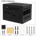 X1200-C1 Accessories
 -
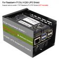 X1200-C1 Application
 -
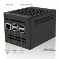 Interface-Front
 -
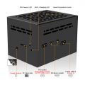 Interface-Rear
 -
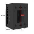 X1200-C1 Dimension


FAQ
Q1: Why does the message "This power supply is not capable of supplying 5A" appear??
X120X series UPS shield can provide enough 5A power supply capacity;
Please set as follows:
Open the Teminal window based on Raspberry Pi OS and execute the following command:
sudo rpi-eeprom-config -e
Add PSU_MAX_CURRENT=5000 at the end of the file that reads like this:

Press Ctrl-O, then enter, to write the change to the file.
Press Ctrl-X to exit nano (the editor).
Reboot your Raspberry Pi 5 to make the change take effect.
Note: If you are using other OS like Ubuntu, please flash Raspberry Pi OS first, and then re-flash other OS such as Ubuntu etc after completing the above settings.
If you are using USB peripherals that need to be powered from the RPi5's USB port, don't forget to enable the following settings to ensure that the RPi5's USB port's current output is not limited:
Add usb_max_current_enable=1 in the /boot/firmware/config.txt file.
Q2. Why am I seeing an "Undervoltage Detected" warning?
A:Regarding the low voltage warning issue(Please refer to Q1 to check whether the connection is installed correctly):
- Please carefully check whether your hardware installation is secure and if the pogo pins are making proper contact. We have had cases where customers found that loose brass standoffs caused poor contact with the pogo pins, leading to the low voltage warning.
- It may be caused by an OS update. Please confirm whether you have recently updated the OS or if your OS system updates automatically.
- Please run the command:
vcgencmd pmic_read_adcand provide us with the result. Alternatively, use a multimeter to measure the voltage value of PIN2. As shown in the figure

pi@geekworm:~ $ vcgencmd pmic_read_adc
 3V7_WL_SW_A current(0)=0.00097593A
   3V3_SYS_A current(1)=0.13955800A
   1V8_SYS_A current(2)=0.25374180A
  DDR_VDD2_A current(3)=0.01854267A
  DDR_VDDQ_A current(4)=0.00049020A
   1V1_SYS_A current(5)=0.25276590A
    0V8_SW_A current(6)=0.34547920A
  VDD_CORE_A current(7)=0.87514000A
   3V3_DAC_A current(17)=0.00024420A
   3V3_ADC_A current(18)=0.00024420A
   0V8_AON_A current(16)=0.00341880A
      HDMI_A current(22)=0.02063490A
 3V7_WL_SW_V volt(8)=3.70534400V
   3V3_SYS_V volt(9)=3.31467300V
   1V8_SYS_V volt(10)=1.80024200V
  DDR_VDD2_V volt(11)=1.11355200V
  DDR_VDDQ_V volt(12)=0.60109830V
   1V1_SYS_V volt(13)=1.10622600V
    0V8_SW_V volt(14)=0.80109810V
  VDD_CORE_V volt(15)=0.72017020V
   3V3_DAC_V volt(20)=3.31318300V
   3V3_ADC_V volt(21)=3.31684600V
   0V8_AON_V volt(19)=0.80029220V
      HDMI_V volt(23)=5.19920000V
     EXT5V_V volt(24)=5.20322000V
      BATT_V volt(25)=0.00000000V
Please check the voltage value of EXT5V_V line
Q3. How to disable/enable the 5V output of the UPS when the RPi 5 is turned off?
A: Editing the EEPROM configuration
From the command line or Terminal window start by running the following command :
sudo rpi-eeprom-config -e
Set POWER_OFF_ON_HALT to 0 or 1 like this:
1: disable 5v outputs
0: enable 5v outputs
Press Ctrl-O, then enter, to write the change to the file.
Press Ctrl-X to exit nano (the editor).
Reboot your Raspberry Pi 5 to make the change take effect.
Q4: How to disable auto power on feature on X1200?
A: When you connect an external power supply, the UPS board will automatically power on the Pi 5 motherboard while it starts charging, this feature is called auto power on, considering that some customers need to disable this feature, so we have also disclosed the following solution to disable it: please use a soldering iron to remove the resistor indicated by the arrow in the illustration.

PS: We don't think you need to remove the resistor to disable 'AUTO ON' function. Since there is an onboard switch, if you don't want AUTO ON, just press the switch to completely cut off the power.
WARNING: Please consider the following risks before removing this resistor:
- Do not operate if you are not a professional user
- The removal operation may damage the MCU, so please be careful with the operation.
- Once you remove this resistor by yourself, you will lose the warranty of this product. We no longer offer any warranty for this product.
- Once you remove this resistor, you can only turn on the power output by pressing the on-board switch.
Q5: How to disable auto power on feature on X1201?
A: When you connect an external power supply, the UPS board will automatically power on the Pi 5 motherboard while it starts charging, this feature is called auto power on, considering that some customers need to disable this feature, so we have also disclosed the following solution to disable it: please use a soldering iron to remove the resistor indicated by the arrow in the illustration.

PS: We don't think you need to remove the resistor to disable 'AUTO ON' function. Since there is an onboard switch, if you don't want AUTO ON, just press the switch to completely cut off the power.
WARNING: Please consider the following risks before removing this resistor:
- Do not operate if you are not a professional user
- The removal operation may damage the MCU, so please be careful with the operation.
- Once you remove this resistor by yourself, you will lose the warranty of this product. We no longer offer any warranty for this product.
- Once you remove this resistor, you can only turn on the power output by pressing the on-board switch.
Q6: How to disable auto power on feature on X1202?
A: When you connect an external power supply, the UPS board will automatically power on the Pi 5 motherboard while it starts charging, this feature is called auto power on, considering that some customers need to disable this feature, so we have also disclosed the following solution to disable it: please use a soldering iron to remove the resistor indicated by the arrow in the illustration.

PS: We don't think you need to remove the resistor to disable 'AUTO ON' function. Since there is an onboard switch, if you don't want AUTO ON, just press the switch to completely cut off the power.
WARNING: Please consider the following risks before removing this resistor:
- Do not operate if you are not a professional user
- The removal operation may damage the MCU, so please be careful with the operation.
- Once you remove this resistor by yourself, you will lose the warranty of this product. We no longer offer any warranty for this product.
- Once you remove this resistor, you can only turn on the power output by pressing the on-board switch or external power switch.
Q7: How to disable auto power on feature on X1203?
A: When you connect an external power supply, the UPS board will automatically power on the Pi 5 motherboard while it starts charging, this feature is called auto power on, considering that some customers need to disable this feature, so we have also disclosed the following solution to disable it: please use a soldering iron to remove the resistor indicated by the arrow in the illustration.

PS: We don't think you need to remove the resistor to disable 'AUTO ON' function. Since there is an onboard switch, if you don't want AUTO ON, just press the switch to completely cut off the power.
WARNING: Please consider the following risks before removing this resistor:
- Do not operate if you are not a professional user
- The removal operation may damage the MCU, so please be careful with the operation.
- Once you remove this resistor by yourself, you will lose the warranty of this product. We no longer offer any warranty for this product.
- Once you remove this resistor, you can only turn on the power output by pressing the on-board switch or external power switch.
Q8: Why is the RPi5 LED still on and red after the UPS is turned off?
A: Please set as follows:
Open the Teminal window based on Raspberry Pi OS and execute the following command:
sudo rpi-eeprom-config -e
Change the setting of POWER_OFF_ON_HALT from 0 to 1
Press Ctrl-O, then enter, to write the change to the file.
Press Ctrl-X to exit nano (the editor).
Reboot your Raspberry Pi 5 to make the change take effect.
Q9: What battery is recommended for this UPS shield?
A: Please use high quality batteries from Samsung 35E 18650 lithium battery, Panasonic NCR18650B, Toshiba, etc. Do not use the battery with built-in protection circuit because it will limit the discharge current.
For the X1203 shield:
If using a lithium battery, the required voltage is 3.7V;
If using a battery pack or battery holder, please make sure it is a parallel battery pack. Please use a high-quality battery holder with thick and durable connection cables. Using a low-quality battery holder with thin or poorly connected wires may cause the X1203 to malfunction or fail to operate as expected.
There are 2 XH2.54-2P battery connectors on board, it is recommended to use the same type of battery.

Q10: Run sudo i2cdetect -y 1, can't find I2C address 0x36?
A:
1. Make sure you enable i2c interface, refer to How to enable I2C
2. The UPS connects to the Pi GPIO via pogo pins, If the I2C address (0x36) is not detected, Please clear the leads of pin 3 and pin 5 on the GPIO header from the bottom of the Raspberry Pi PCB and install again, and also check if the pogo pin of ups shield is in close contact with the pad position of PI 5(you can adjust the [pogo pin] position).

There won't be any other problems, it's this poor contact that's causing it.

Q11. How do you disable the X1202 auto-shutdown when you use it standalone (not installed on a RPi5)?
A:

Q12. X1203 UPS voltage drops / low voltage warning appears?
A:
1.Powering the X1203 via Type C connector with / without the batteries,Pls check if you still have the issue.
2.Please clear the test pad on the Pi's PCB bottom which is used for connecting the X1203 for 5V power delivery.

Q13. Documentation about the I2C registers:
A:
Q14. Why does the RPI 5 lose power within a few seconds after pressing the power button on the X120x UPS?
A:
Please note: If the UPS does not detect the RPi5, it will automatically shut down within 3 seconds. So you need to install the RPi 5 on the UPS and make sure that the RPi5 has good contact with the UPS's pogo pins.
Q15. Which product should I choose if I can’t connect to a Raspberry Pi via pogo pins?
A:
For the X12-UPS series, we recommend the X1206 – models from X1200 to X1205 do not support this usage. The X120- UPS series auto-powers off when no Raspberry Pi 5 is detected, while the X1206 can be set to "Always Power On" mode and keeps working even if the Raspberry Pi is shut down. Please refer to Interface ⑩_ALON in the picture.

You can also consider the X-UPS1. It features a GPIO Pin-Connected standalone design with high flexibility for installation and adaptation (refer to the picture).

Q16. Questions about reverse-polarity protection
Q. Does the X1200 series have reverse-polarity protection? What happens if I insert a single cell backward?
A: Yes. The X1200 series features hardware-level reverse-polarity protection circuitry. If only one 18650/21700 cell is installed and it is inserted backward, the board will immediately enter a protection state and disable all functionality. This blocks reverse current from reaching or damaging the downstream charging and system circuits.
Q.What happens if one cell is inserted correctly and the other is reversed for X1200?
A: The board is safely protected by dedicated inline fuses. Each individual battery slot on the X1200 is integrated with its own 5A rated fuse. If a user inserts one cell correctly and the second cell backward, the massive loop current generated between the two cells will instantly blow the 5A fuse of the reversed slot. This isolates the faulted battery holder and completely protects the rest of the board and the correctly installed cell from damage.
⚠️ Warning: Despite these robust hardware safeguards, always ensure the correct polarity when installing batteries. Relying on protection states should be a last resort.
Q: What are the exact over-current and short-circuit protection thresholds for X1200?
A: The X1200 utilizes a two-tier protection architecture to handle short-circuits and over-current conditions:
- Slot Level: Each 18650 battery holder is inline with a bidirectional 5A fuse that blows immediately if individual slot current exceeds 5A.
- System Level: After the two slots parallel together, the power rail passes through a dedicated battery protection IC. The hardware over-current trip threshold for this IC is 10.5A to 19.5A.