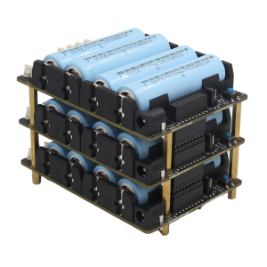
X-UPS1

From Geekworm Wiki
Jump to navigation Jump to search

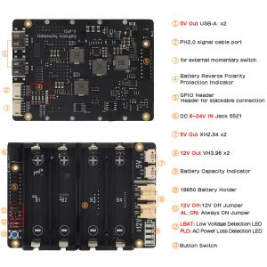
X-UPS1 V1.3 Interface Schematic
Sackable & universal UPS shiled, 12V & 5V dual output voltage for all SBC
X-UPS1 V1.3
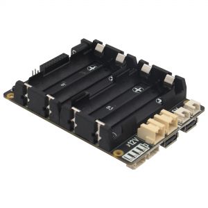
X-UPS1 V1.3
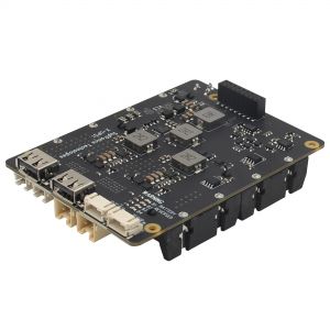
X-UPS1 V1.3
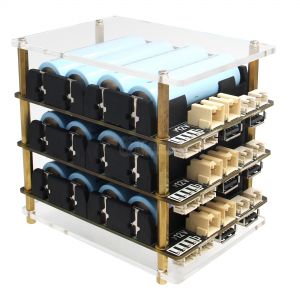
X-UPS1 UPS with Acrylic Plate

Overview

The X-UPS1 is an universal stackable uninterruptible power supply (UPS) shield for most Single-Board Computers (SBC) that uses 12Vdc or 5Vdc. The UPS ensures that in event of power interruption, a battery or any other power source will intervene without any effect on your board.

Our convenient stackable design allows you to connect several UPS modules on your boards to provide long-lasting & higher output power.

Features

For use with

Most Single-Board Computers (SBC) that uses 12Vdc or 5Vdc,

  • SBC Example: Orange Pi 5 / Jetson Nano / Raspberry Pi / Tinker Board / Arduino etc.
Key Features

Power Input

  • Integrated highefficiency stepdown DC/DC converter
  • Wide 6V to 24V operating input range
  • Up to 95% Efficiency
  • Allows powering from a car, a solder pannel and other power sources
  • Most common power input jack: 5.5x2.1mm

Power Output

  • Provides dual 12Vdc & 5Vdc or single 5Vdc output
  • Each board provides max 12V/3A or 5V/3A power backup
  • Can be stacked to increase output current and battery life
  • Total output current could be 3A multiplied by the quantity of boards.For example, one X-UPS1 can output 3A, two are 6A, three are 9A, and so on
  • Reverse Current Protection
  • Integrate Advanced Power MOSFET with Equivalent of 7mΩ RDS(ON) to reduce power loss

Battery Charging

  • Supports 3000mA fast battery charging
  • Battery over current protection and over voltage protection
  • Protection of battery cell Reverse Connection
  • Lowbattery detection (LED and 3.3V level output)
  • Onboard 4 green LEDs indicate battery charging and discharging levels of 25%, 50% , 75% and 100%
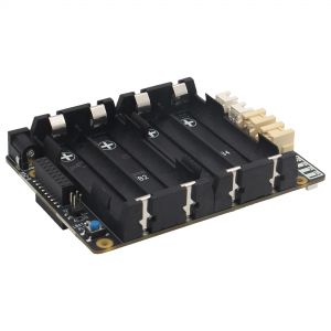
  • 18650 4cell lithium Ion holders
  • When stacked, multiple power adapters can be used to charge at the same time

Power Control

  • Onboard push button to control power on /off (PressON, Hold the button pressed at least 3s OFF )
  • Onboard LEDs shows the status of power output
  • AC power loss or power adapter failure detection (LED and 3.3V level output)
  • Jumper setting to enable Auto power on when power applied or restored
  • Jumper setting to disable 12V output
  • Ultralow standby power consumption to maximize battery life
  • Advanced system powerpath management avoids batteries frequent charging and discharging

Misc

  • Power output connectors : VH3.96 x2 (12V) / XH2.54 x2 (5V) / USB TypeA x2 (5V)
  • PH2.0-4P for external power switch
  • PH2.0-4P for LBAT (low battery) and PLD (AC power loss) detection)
  • LBAT: A high level will be triggered when the battery voltage is lower than or equal to 3V (You can't modify this threshold of 3V)
  • PLD: (AC power loss detection), When the external power supply is disconnected, it will trigger a high level, and the indicator light will be on
  • You can program it yourself to read the above PLD and LBAT pin GPIO signals to achieve your own more advanced functions such as low battery monitoring and power failure detection, which can be referred to the plsd.py file of X708-script. We do not provide example programs
Spec
  • Power input (Single board) : 6-24Vdc ±5%, ≥3A
  • UPS output voltage : 12Vdc ±5%, 5.1Vdc ±5%
  • UPS output current (Single boards) : Max 3A
  • UPS output current (Stackable boards) : 3A x No. of the boards
  • UPS charging current (Single board) : 2.3~3.2A
  • Terminal Battery Voltage : 4.24V
  • Battery Recharge Threshold : 4.1V
  • Battery low detection: ≤3V (when battery voltage ≤2.4V, the power will be cut off to prevent over-discharge; and power supply will be restored when the battery voltage returns to around 3.1V)
Note

Notes for stackable application:

  1. All power input are connected together via the 18-pin female header, output current is subject to the quantity of boards.
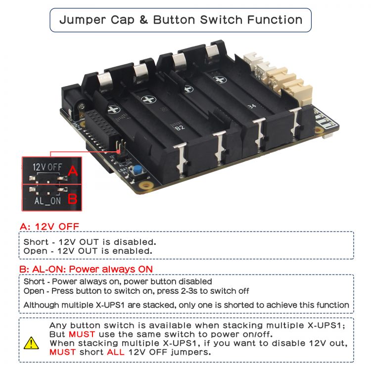
  2. You can use same one board to turn on/off all stackable boards. (be noted that which board you press the button to turn on, also must the same board to turn off.)
  3. Only one AL_ON jumper caps be shorted to enable Always Power On when stacked multiple x-ups1 shields.
  4. When stacking more than 2 X-UPS1 boards, if you want to disable the 12V OUT, you have to short ALL the 12V OFF. If one of them is not shorted, the 12V OUT will occur.

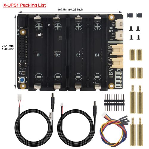
Packing List

  • 1 x X-UPS1 Expansion Board
  • 1 x VH3.96 to DC5525 Cable (50cm length, to 12V output)
  • 1 x XH2.54 to DC5521 Cable (50cm length, to 5V output)
  • 1 x 4Pin PH2.0 to dupont cable (30cm length, this is a signal & 5V Output Cable)
  • 1 x Adapter DC5521 Female to Type-C Male (New added on Oct., 17th, 2024)
  • 1 x GPIO Header
  • 2 x Jumper link Pitch 2.54mm
  • 4x Spacer F/F M2.5x10mm
  • 4 x Spacer M/F M2.5x25+6mm
  • 4 x Screw M2.5 x 5mm

X-ups1-Packing-List.jpg

User Manual

1. X-UPS1 V1.3 Jumper Cap & Button Switch Guidance:

Jumper Cap & Button Switch Function

2. Guide based on the Raspberry Pi 5;

If you are using the X-UPS1 with the Raspberry Pi 5, you will need to do the following configuration on the Raspberry Pi 5:

From the command line or Terminal window start by running the following command :

sudo rpi-eeprom-config -e
	

Change the setting of POWER_OFF_ON_HALT from 0 to 1 ,

Add PSU_MAX_CURRENT=5000 at the end of the file that reads like this:

X120x setting1.png

Then reboot your Raspberry Pi 5 to make the change take effect.

sudo reboot

Application

Compatible with Most Single Board Computers (SBC) that uses 12Vdc or 5Vdc, SBC Example: Orange Pi 5 / Jetson Nano / Raspberry Pi / Tinker Board / Arduino etc.

PCB Dimension

X-UPS1 Dimensions source file (DXF): File:X-UPS1-PCB.dxf - You can view it with Autodesk Viewer online

SAFETY INSTRUCTIONS AND WARNINGS

  • You must read these safety instructions and warnings before charging your batteries.
  • Lithium Polymer and Li-ion batteries are volatile. Failure to read and follow the below instructions may result in fire, personal injury and damage to property if charged or used improperly.
  • Never make wrong polarity connection when charging and discharging battery packs. Always double check polarity of battery's connector to make sure "+" to "+" and "-" to "-".
  • Do not mix and use old batteries and new batteries, or batteries with different brand names.
  • Lithium batteries has it's cycle life, please replace old battery with new one when it reaches it's service life or when it is two year old, whichever comes first.
  • When charging Battery Pack, please put battery in a fire proof container. Please don't leave the X-UPS1 on the wood material or carpet and unattended.
  • Must keep the X-UPS1 away from children.
  • Please watch Main Video and Tutorial Video regarding 18650 batteries at: https://www.staysafebattery.com/en/
  • Battery Recommend for X-UPS1 board, please refer to: File:NCR18650B.pdf

FAQ

Q: About X-UPS1 External PH2.0-4P Switch

A: The X-UPS1 has a JST PH2.0-4P switch connector reserved to allow you to use an external reset switch to fulfill the function of the on-board switch in appropriate scenarios. Care needs to be taken to use the correct wiring sequence for your momentary self-reset switch, please refer to the silkscreen description on the PCB board, you can refer to PSW19 or purchase it from https://geekworm.com/products/power-control-switch-for-x820-or-x735

Q: Can I use a 20V battery to power the X-UPS1?

A: Actually the DC/DC chipset can withstand 24V and we tested with a lab power supply and it worked. here is the link of the datasheet. https://www.richtek.com/assets/product_file/RT7259/DS7259-01.pdf

but to be safe, we recommend that using the 12V batteries to power the UPS boards.

Add your comment
Geekworm Wiki welcomes all comments. If you do not want to be anonymous, register or log in. It is free.


Anonymous user #17

23 days ago
Score 0++
Hi! Great product, mine is getting delivered tomorrow. Are 3D CAD files available for this UPS?

Lisa

23 days ago
Score 0++

Hi,Sorry, there is no 3D CAD file;

you can refer to X-UPS1#PCB Dimension

Anonymous user #18

21 days ago
Score 0++
OP here. The DXF drawing is detailed and the layers are broken out, so with a set of calipers to measure the heights of components, it was pretty quick work to make a good CAD drawing.

Anonymous user #16

23 days ago
Score 0++

already sent a email to "support@geekworm.com", with title "X-UPS 1 smoking issue + product prototype"

no response yet, please follow up.

Anonymous user #16

24 days ago
Score 0++

Hi,

I want to know what limits the DC5521 charging port current to >=3A? Is it because the DC5521 port is only rated for 3A? In that case If I want to have higher charging current, can I solder cable directly on it?

I am developing a product, have more question on this, please add me wechat and discuss further as soon as possible, thank you!

wechat id: s0313045

Lisa

23 days ago
Score 0++
Hello,Please contact us by email and tell us your order number. support@geekworm.com;

Harry

23 days ago
Score 0++

There is no limit on the input current. For safety reasons, X-UPS1 will only limit the charging current to 3A.

Please email to us.

Anonymous user #16

24 days ago
Score 0++

To give more information on this: I used two UPS boards stacked together/ I have supplied 12v to power input port of both boards at the same time, and everything works.

But once I do the same thing, but with 20v, once I supply 20v to power input port of both UPS board at the same time, it smokes near the power input end, a small black square component near the power input port, on both boards is burning red.

Harry

23 days ago
Score 0++

The 20V power supply may have surge voltage or excessive ripple voltage.

The power chip can support up to 24V

Anonymous user #16

24 days ago
Score 0++

Following the question below:

In the datasheet/manual above, it clearly state that "Battery Charging - When stacked, multiple power adapters can be used to charge at the same time"

So why does it smoke when I supply 20v to power input port of both boards at the same time?????

Harry

23 days ago
Score 0++

The 20V power supply may have surge voltage or excessive ripple voltage. Check your 20V power supply and do not use the power supply for LED strips.

The power chip can support up to 24V.

Anonymous user #14

24 days ago
Score 0++

Hi, I have 2 of these UPS stacked together, and I provide 20v to both board's input port and smoke comes out near the input port of both boards.

=

So how am I suppose to provide 6A for the UPS, when one input port only accepts 3A?

If I am only suppose to power it through one of the input port, will it be able to take in 6A?

The downstream device that UPS is powering will takes 6A (small computer), so I need the (2x stacked together UPS) to be able to draw 6A from the power supply. How can I do it?

Anonymous user #15

one month ago
Score 0++
Does this UPS cut power automatically if voltage is lower than 3v??

Lisa

one month ago
Score 0++
Hi,It won't shut down, but a high level will be triggered when the battery voltage is lower than or equal to 3V.

Anonymous user #14

one month ago
Score 0++

Does this UPS handles and protect against reverse current on its output port?

If there is current coming back from the output port, will the board still be able to handle it?

Harry

one month ago
Score 0++
X-UPS1 can block reverse current, but it is not recommended to do so. UPS is a power supply device.

Anonymous user #13

one month ago
Score 0++

In addition to the previous question:

I plan to use two of these UPS boards, stacked together whole having power input (12V 10A) power supply connected for most of the time.

The idea is to continue provide power to the 12V 4A motor, even when the power supply is disconnected.

Will this work? With the power input connected, if the output side is drawing 4A, it can still draw 4A from the power supply, right?

Anonymous user #13

one month ago
Score 0++

Also, my current plan is to use two of these UPS board, stacked together to provide UPS capability to a 12v 4a motor, will there be any issue?

Also if the system is not powered, and I turn the motor, the motor generate power. Does the board protect against any "backward" current produced by rotating the downstream motor??

Lisa

one month ago
Score 0++
Sorry we haven't tested it with the motor.

Anonymous user #13

one month ago
Score 0++

Following the previous question:

If I stack 2 of these boards together:

I know output current is subject to the quantity of boards.

But can I use 12V output (VH3.96 x 2) port coming out from both boards, so (VH3.96 x 4) all at once to get the full current output?

Lisa

one month ago
Score 0++
Yes you can use the 12v output from 2 boards since they are wired in parallel.

Anonymous user #13

one month ago
Score 0++

If I stack 2 of these boards together.

1) Can I supply power input through both the DC barrel connectors on both boards when stacked?

2) Can I use 12V output from both boards, to get the full current output? 3A x 2boards?

Lisa

one month ago
Score 0++

Hi,

1)All power input are connected together via the 18-pin female header,no need to power both boards at the same time.

2)output current is subject to the quantity of boards.

Anonymous user #12

one month ago
Score 0++
Can you please explain how to wire a LED to the PLD LBAT port?

Harry

one month ago
Score 0++
  • LBAT: A high level will be triggered when the battery voltage is lower than or equal to 3V (You can't modify this threshold of 3V)
  • PLD: (AC power loss detection), When the external power supply is disconnected, it will trigger a high level, and the indicator light will be on
It is clearly written here.

Anonymous user #11

2 months ago
Score 0++
What is the height of the board with batteries ?

Lisa

2 months ago
Score 0++
Hi,The height of the expansion board with battery is about 21mm; the distance between the first and second layers is 25mm.

Anonymous user #10

2 months ago
Score 0++
Where can I find the pin-out detail for the 18 pin stacking header? I am using with ESP32 boards and would like to interface through I2C, which I hope is exposed there.

Lisa

2 months ago
Score 0++
Hello,X-UPS1 is a universal UPS power management board, no pin diagram.

Anonymous user #9

4 months ago
Score 0++
Is it possible for one of the boards in a stacked configuration to output 5V while the other board outputs 12V, or for a single board to output both 5V and 12V simultaneously?

Lisa

4 months ago
Score 0++
Hi,single board to output both 5V and 12V simultaneously. Provides dual 12Vdc & 5Vdc or single 5Vdc output.

Anonymous user #8

5 months ago
Score 0++
Your instruction is confusing, it says "MUST ALL 12 OFF jumper caps be shorted to disable 12V output when stacked multiple x-ups1 shields." Does it mean that X-UPS1 can only output 5v when multiple x-ups1 stacked?? Another words, Can X-UPS1 output 12v when 2 or more X-UPS1 stacked?

Lisa

5 months ago
Score 0++

Sorry, we've updated the description. The point we were trying to make was:

when stacking more than 2 X-UPS1 boards, if you want to disable the 12V OUT, you have to short ALL the 12V OFF. If one of them is not shorted, the 12V OUT will occur.

Anonymous user #7

6 months ago
Score 0++
For the external switch the description on the PCB says power(black), Gnd(red), Gnd(yellow), and SW(blue) In that exact order on a psw19 or any 4 prong switch you have positive, negative, NO, and C Please show wire diagram for of the PH2.0 signal cable connector and the external momentary switch

Lisa

5 months ago
Score 0++
Hi,please refer to PSW19---Power Switch Wiring Diagram

Anonymous user #6

7 months ago
Score 0++
When multiple boards are stacked can I use the outputs on all boards, or only the first? Thanks!

Lisa

7 months ago
Score 0++
Hello,you can use the output of one of the UPS boards

Anonymous user #5

10 months ago
Score 0++
Can you post example usage of the PH2.0 signal cable connector and the external momentary switch connector.

Anonymous user #4

11 months ago
Score 0++
Hello, button top of flat top 18650? Protection circuit? For US users, it's be helpful to link to batteries on imrbatteries.com, as they specify many details like that.

Walker

11 months ago
Score 0++

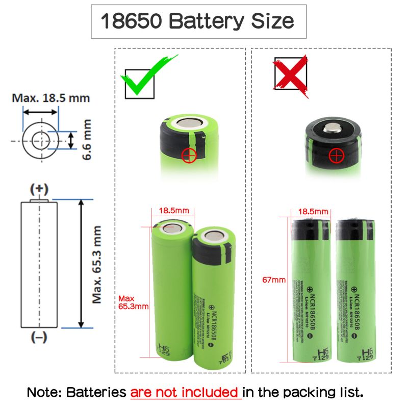
Pls use high quality batteries from PANPASONIC, Toshiba, etc.

Do not use the battery with built-in protection circuit.

18650 battery size-2.jpg

Anonymous user #3

14 months ago
Score 0++
Is it possible to read the voltage and capacity in python?

Walker

14 months ago
Score 0++
Hello, Onboard 4 green LEDs indicate battery charging and discharging levels of 25%, 50%, 75% and 100%. Only these ranges can be displayed.

Walker

14 months ago
Score 0++
Hello, it’s not possible. It can only display a range and cannot read specific values in python.

Anonymous user #3

14 months ago
Score 0++
GPIO pin layout?

Anonymous user #2

14 months ago
Score 0++
Please tell me the operating temperature range and storage temperature range.

Walker

14 months ago
Score 0++
Hello, usually between 0-50 degrees

Anonymous user #1

16 months ago
Score 0++
Can you PLEASE just post the physical dimensions. The DXF file does not self-calibrate. It's really weird you don't just have the dimensions on the product description.