Difference between revisions of "X680"
| (144 intermediate revisions by 3 users not shown) | |||
| Line 2: | Line 2: | ||
[[File:X680-IMG-5547.jpg|thumb|right|x680 kvm over ip front view]] | [[File:X680-IMG-5547.jpg|thumb|right|x680 kvm over ip front view]] | ||
[[File:X680-IMG-5546.jpg|thumb|right|x680 kvm over ip rear view]] | [[File:X680-IMG-5546.jpg|thumb|right|x680 kvm over ip rear view]] | ||
| + | [[File:X680-IMG-5531-diagram.jpg|thumb|right|x680 diagram & size]] | ||
| + | [[File:X680-IMG-5617.jpg|thumb|right|x680 kvm over ip Internal view]] | ||
[[File:X680-IMG-5620.jpg|thumb|right|x680 kvm over ip internal view]] | [[File:X680-IMG-5620.jpg|thumb|right|x680 kvm over ip internal view]] | ||
| + | [[File:X680-IMG-5615.jpg|thumb|right|x680 kvm over ip inner view]] | ||
| + | [[File:X680-IMG-5531-acce.jpg|thumb|right|x680 packing list]] | ||
| + | |||
==Overview== | ==Overview== | ||
| − | This | + | '''Update:''' |
| + | |||
| + | X680 is upgraaded from V1.3 to V1.5 from June 2024, adding the following features: | ||
| + | * Supports switching between hosts in the web UI | ||
| + | * Supports HDMI input resolutions up to 1920x1080 at 60Hz | ||
| + | PS: Need to do the corresponding configuration | ||
| + | |||
| + | |||
| + | This X680 is a member of the [[PiKVM]]<ref>PiKVM © belongs to https://pikvm.org</ref> family, it is a 4-port IP KVM Switch empowers you to securely manage up to four computers/servers remotely from almost anywhere using the internet or your local area network (LAN). | ||
Unlike software solutions that require installation and work through your server's operating system, this IP KVM Switch offers KVM control from the BIOS-level onward. Reboot, monitor the entire boot process, and interact with your connected system easily, while the integrated remote ATX power control allows you to switch the machine on/off, reset it, and monitor power & storage LED activity remotely. Featuring 3 additional USB2.0 ports for peripheral sharing (USB storage, CD ROM, etc.), allowing file transfers and disk emulation for remote application and OS installs. | Unlike software solutions that require installation and work through your server's operating system, this IP KVM Switch offers KVM control from the BIOS-level onward. Reboot, monitor the entire boot process, and interact with your connected system easily, while the integrated remote ATX power control allows you to switch the machine on/off, reset it, and monitor power & storage LED activity remotely. Featuring 3 additional USB2.0 ports for peripheral sharing (USB storage, CD ROM, etc.), allowing file transfers and disk emulation for remote application and OS installs. | ||
The IP KVM Switch supports direct switching through buttons on front panel and hotkey through keyboard connected to the special USB 1.1 port. it also supports remote hotkey switching between computers for easy monitoring. | The IP KVM Switch supports direct switching through buttons on front panel and hotkey through keyboard connected to the special USB 1.1 port. it also supports remote hotkey switching between computers for easy monitoring. | ||
| + | |||
| + | '''About the USB OTG port of X680:''' The USB OTG port is used to control the keyboard and mouse. However, when the OTG port is in use, it prevents the control of the keyboard and mouse. The X680 utilizes the CM4 and does not have additional USB ports for connecting a USB drive. | ||
==Features== | ==Features== | ||
* Based on the Raspberry Pi Compute Module 4 and Compatible with all variants | * Based on the Raspberry Pi Compute Module 4 and Compatible with all variants | ||
| − | * Designed especially for PiKVM ( Raspberry | + | * Designed especially for PiKVM ( Raspberry Pi based KVM over IP) |
| + | * <span style="color:red;">Only compatible with '''PiKVM V3 OS''', NOT support '''V4'''</span> | ||
* Control up to 4 USB HDMI computers/servers remotely over an IP network or the internet | * Control up to 4 USB HDMI computers/servers remotely over an IP network or the internet | ||
| − | * Full remote | + | * Full remote BIOS level control access the BIOS, and have full control over the keyboard and mouse |
* Supports four HDMI inputs, four USB inputs and four RJ45 ports for ATX power control | * Supports four HDMI inputs, four USB inputs and four RJ45 ports for ATX power control | ||
* Integrated USB hub for peripheral sharing and file transfer of USB 2.0 devices (backwards compatible with USB 1.1 and 1.0 devices) | * Integrated USB hub for peripheral sharing and file transfer of USB 2.0 devices (backwards compatible with USB 1.1 and 1.0 devices) | ||
| Line 20: | Line 36: | ||
* Supports remote hotkey switching between computers for easy monitoring | * Supports remote hotkey switching between computers for easy monitoring | ||
* Supports direct switching through buttons and hotkey through keyboard (Keyboard must be connected to USB 1.1 port) | * Supports direct switching through buttons and hotkey through keyboard (Keyboard must be connected to USB 1.1 port) | ||
| − | * Supports HDMI input resolutions up to 1920x1080 | + | * Supports HDMI input resolutions up to 1920x1080 |
* 0.96 inch OLED display with name, IP address, temperature, CPU load, and uptime | * 0.96 inch OLED display with name, IP address, temperature, CPU load, and uptime | ||
* Hardware Real Time Clock (RTC) with CR1220 coin battery socket | * Hardware Real Time Clock (RTC) with CR1220 coin battery socket | ||
| Line 30: | Line 46: | ||
* Equipped with cooling fan that allows the heat from CM4 to dissipate | * Equipped with cooling fan that allows the heat from CM4 to dissipate | ||
* Supports booting from MicroSD, CM4 eMMC and faster M.2 2280 NVME SSD | * Supports booting from MicroSD, CM4 eMMC and faster M.2 2280 NVME SSD | ||
| + | |||
| + | ==How to Power== | ||
| + | * Power Input: 5.1Vdc +/-5% , ≥4A; (DC5525 5V 4A power adapter with US & EU plug is included!!!) | ||
| + | |||
| + | ==How to Cool== | ||
| + | X680 equipped with an active cooling fan board (X680-A1) that can cool your Raspberry Pi CM4. | ||
| + | <gallery> | ||
| + | File:X650-IMG-5480.jpg|X680-A1 | ||
| + | </gallery> | ||
| + | |||
| + | If you think it noisy, you can replace it with a [[C235]] heatsink. | ||
==Packing List== | ==Packing List== | ||
| − | * '''1 x | + | * '''1 x X680 4-port IP KVM Switch Kit''' |
* 4 x USB2.0 A to B Cable (1.5m/59.06inch) | * 4 x USB2.0 A to B Cable (1.5m/59.06inch) | ||
| − | * '''1 x | + | * '''1 x DC 5V 4A Power Adapter '''(With US/EU Plug) |
| − | * 1 x | + | * 1 x Screws Pack |
| − | * 1 | + | |
| − | * | + | '''A note about this kit listing:''' |
| + | * 1. X630-A5 is only suitable for devices with ATX CONTROL such as desktops, servers, etc. | ||
| + | * 2. If you are using a device that supports ATX CONTROL, we recommend that you purchase X630-A5 and RJ45 ATX control cable kit; | ||
| + | * 3. X630-A5 is installed inside the ATX CONTROL device, one X630-A5 only supports one device; X680 supports simultaneous control of 4 devices | ||
| + | * 4. ATX CONTROL can support remote startup, shutdown, restart and other functions | ||
| + | * 5. You need to buy the appropriate length HDMI cable by yourself, because we don't know what length HDMI cable you need | ||
| + | * 6. The X680 Kits <span style="color:red;>DO NOT</span> include '''CM4''' module also. | ||
| + | |||
| + | '''Additional accessories to purchase yourself:''' | ||
| + | * Raspberry Pi Compute Module 4 CM4 | ||
| + | * A minimum 16 Gb class 10 memory card is recommended.(In fact, you don't need Micro SD card if you use CM4 with eMMC, because you can flash the firmware into the eMMC.) | ||
| + | |||
| + | '''ATX Conrol cable(Not included):''' | ||
| + | |||
| + | You can make your own ATX control cable, in fact, it is a normal Ethernet cable, and the requirements must be '''568B''' line sequence | ||
| + | |||
| + | [[File:RJ75-568B.png]] | ||
| + | |||
| + | '''RJ45 Pinout of KVM:''' | ||
| + | |||
| + | [[File:RJ45-PINOUT.png]] | ||
| + | |||
| + | ==Hardware Connection & installation== | ||
| + | Refer to: https://youtu.be/ukHCz1RsFx4 | ||
| + | {{#ev:youtube|https://youtu.be/ukHCz1RsFx4}} | ||
| + | |||
| + | X680 HDMI port display information, according to the test: | ||
| + | |||
| + | [[File:HDMI-OUT-INFO-1.jpg|700px|X680 HDMI port info]] | ||
==User Manual== | ==User Manual== | ||
| − | ===Computers/Servers Switching | + | [http://about:blank PiKVM] is a Free and Open Source Software that is released under the GPLv3 license. The Operating System (OS) image provided here is solely for the purpose of hardware testing. For commercial use, it is advised to directly contact the developers of PiKVM. |
| − | Press to select PC1/PC2/PC3/PC4 through buttons on front panel. the corresponding LED located on the right of the button will be on if a PC is selected. the PC1 will be automatically selected when power applied or restored. | + | |
| + | The development of this software would not be possible without the financial backing of the community. Contributions play a vital role in sustaining and advancing the project. If you wish to contribute, you can visit the PiKVM donation page at https://pikvm.org/donate/. Your support is greatly appreciated and will help in the continuous development and improvement of this software. | ||
| + | |||
| + | ===OS Download & Installation=== | ||
| + | 1. Firstly, need prepair a micro sd card, a minimum 32/64 Gb class 10 memory card is recommended. If you use a CM4 with eMMC, you don't need a micro sd card. | ||
| + | |||
| + | 2. Download an appropriate OS image for the PiKVM, the url link is https://pikvm.org/download/ or click [https://files.pikvm.org/images/v3-hdmi-rpi4-box-latest.img.xz this one] to download it. (Please use the '''V3 Pre-Assembled''' OS image) | ||
| + | |||
| + | :We recommend that you use the ''''V3 Pre-Assembled'''' version, and this image includes OLED display configuration. | ||
| + | :<span style="color:red;">Only compatible with PiKVM V3 platform OS, NOT support PiKVM V4 Plus & V4 Mini platform!!!</span> | ||
| + | |||
| + | :[[File:Pi4-V3-HAT.png|800px|PiKVM V3 platform]] | ||
| + | |||
| + | ===Flash OS image=== | ||
| + | :1. You can use Raspberry Pi Imager to Flash or the following alternatives tools: | ||
| + | :* [https://etcher.balena.io/ balenaEtcher]: The application runs on Windows, MacOS, and Ubuntu operating systems. | ||
| + | :* [https://i-win32diskimager.com/ Win32 Disk Imager]: This imaging software is designed for Windows machines. | ||
| + | :2. Flash OS image to a microSD memory card by following [https://docs.pikvm.org/flashing_os the simple instructions] or [https://www.raspberrypi.com/documentation/computers/getting-started.html#installing-the-operating-system Official installation tutorial] | ||
| + | |||
| + | :3. Refer to [[#How to flash OS onto the eMMC of CM4? (CM4 with eMMC)?]] if you use the CM4 shield with eMMC. | ||
| + | |||
| + | :4. Then power the device, then open explore to login the pikvm web ui. | ||
| + | * How to flash OS onto the eMMC of CM4? (CM4 with eMMC)? | ||
| + | :1. Short nBOOT Pin, refer to the picture below. | ||
| + | |||
| + | :[[File:X680-IMG-5615-3.jpg|500px]] | ||
| + | |||
| + | :2. Connect CM4 USB port with a Type-A to Type-B cable to your computer as follow: | ||
| + | |||
| + | :[[File:X680-IMG-5546-3.jpg|500px]] | ||
| + | |||
| + | :3. Power the device via PWR DC Jack with 5V Power adaper | ||
| + | |||
| + | :4. Then rerfer to [https://www.jeffgeerling.com/blog/2020/how-flash-raspberry-pi-os-compute-module-4-emmc-usbboot this tutorial] to flash raspberry pi OS | ||
| + | |||
| + | :5. Remove the jumper of nBOOT after flashing is complete, then restart your device; | ||
| + | |||
| + | :'''PS:If you use CM4 with eMMC, then SD card cannot be used.''' | ||
| + | |||
| + | ===Configuring the PiKVM OS=== | ||
| + | * '''Login web UI''' | ||
| + | : Access to PiKVM Web Interface via any browser with the URL '''https://pikvm/''' OR '''https://IP''' address of your ipkvm/, the default user and password is admin/admin | ||
| + | * '''Log into PiKVM and open Terminal program''' | ||
| + | * '''Switch to 'root' user ''' | ||
| + | :<pre>su root</pre> | ||
| + | :then type the password, and the default password is 'root' also. | ||
| + | * '''Switch OS to writable mode''' | ||
| + | :<pre>rw</pre> | ||
| + | |||
| + | * '''Enable RTC''' ('''Only for X680 V1.3''' because v1.3 use the ds1307 chip, Please skip this step if you X680 V1.5 using the same chip pcf8563 with pikvm official product) | ||
| + | :1. Due to different RTC chips with official PiKVM hardware, you still need to '''configure RTC''' to make RTC work normally. | ||
| + | |||
| + | :2. Insert the '''C1220''' button battery. run the following command in web terminal window: | ||
| + | |||
| + | :3. Edit the /boot/config.txt file, and change line <code>dtoverlay=i2c-rtc,pcf8563</code> to <code>dtoverlay=i2c-rtc,ds1307</code> (due to use the different RTC chip). | ||
| + | :<pre>sudo nano /boot/config.txt</pre> | ||
| + | :Then save & '''reboot''' the device; | ||
| + | |||
| + | :Test & setting RTC, write&read the time of Raspberry Pi to RTC DS1307 | ||
| + | <dd> | ||
| + | <pre> | ||
| + | date | ||
| + | sudo hwclock -w | ||
| + | sudo hwclock -r | ||
| + | </pre> | ||
| + | </dd> | ||
| + | |||
| + | *'''Enable OLED display''' | ||
| + | :Run the following command in web terminal window to enable OLED display: | ||
| + | :<pre>systemctl enable --now kvmd-oled kvmd-oled-reboot kvmd-oled-shutdown </pre> | ||
| + | :If you are using <code>PiKVM OS V3 Pre-Assembled</code>, the OLED configuration is already pre-installed, you can ignore this step. | ||
| + | : Rotate the OLED display by 180 degrees (Optional) | ||
| + | :<pre>nano /usr/bin/kvmd-oled</pre> | ||
| + | :Change the line: return {"height": 64, "rotate": '''2'''} to return {"height": 64, "rotate": '''0'''}, then save & exit | ||
| + | |||
| + | * '''Enable pikvm hdmi audio''' | ||
| + | :Refer to [[Enable pikvm hdmi audio]] | ||
| + | |||
| + | *How to boot from NVME SSD? | ||
| + | :1.Prepare the '''Win32 Disk Imager tool''' first, download and install it, refer to:https://sourceforge.net/projects/win32diskimager/ | ||
| + | |||
| + | :2. Insert NVME SSD into the '''USB to NVME ssd adapter''' or [[X876]] | ||
| + | |||
| + | :3. Connect '''USB to NVME SSD adapter''' or [[X876]] to computer through USB A cable, then a USB drive can be recognized in computer. | ||
| + | |||
| + | :4. Open '''Win32 Disk Imager''' tool, then select the '''PiKVM os image file''' and '''USB drive''', then click '''Write''' button | ||
| + | |||
| + | :5. Wait a few minutes for the write process to complete. | ||
| + | |||
| + | :6. Insert NMVE SSD into the X680, then power on (must remove the micro sd card firstly) | ||
| + | |||
| + | *'''Mass Storage Drive''' | ||
| + | :Refer to: https://docs.pikvm.org/msd/ | ||
| + | * '''Check Video Output''' | ||
| + | :<pre>ls /dev/video0</pre> | ||
| + | : Run the above command, if you see anything such as '''/dev/video0''' other than '''file not found''', then it’s available | ||
| + | * <span class="tb_red">'''To support max resolution 1920x1080 60Hz''' (for '''V1.5''' only)</span> | ||
| + | :<pre>nano /boot/config.txt</pre> | ||
| + | :Change the line7 from '''dtoverlay=tc358743''' to '''dtoverlay=tc358743,<span class="tb_red">4lane=1</span>''' | ||
| + | :Save and exit by hitting '''CTRL + X''', answering '''Y''' and hitting Enter when prompted. | ||
| + | |||
| + | :'''Editing the EDID''' | ||
| + | :<pre>nano /etc/kvmd/tc358743-edid.hex</pre> | ||
| + | :Delete existing EDID data, then copy and paste below new EDID data | ||
| + | <dd> | ||
| + | <pre> | ||
| + | 00FFFFFFFFFFFF005262888800888888 | ||
| + | 1C150103800000780AEE91A3544C9926 | ||
| + | 0F505400000001010101010101010101 | ||
| + | 010101010101011D007251D01E206E28 | ||
| + | 5500C48E2100001E8C0AD08A20E02D10 | ||
| + | 103E9600138E2100001E000000FC0054 | ||
| + | 6F73686962612D4832430A20000000FD | ||
| + | 003B3D0F2E0F1E0A202020202020014F | ||
| + | 020323454F041303021211012021A23C | ||
| + | 3D3E1F102309070766030C00300080E3 | ||
| + | 007F8C8C0AD08A20E02D10103E9600C4 | ||
| + | 8E210000188C0AD08A20E02D10103E96 | ||
| + | 00138E210000188C0AA01451F0160026 | ||
| + | 7C4300138E2100009800000000000000 | ||
| + | 00000000000000000000000000000000 | ||
| + | 00000000000000000000000000000087 | ||
| + | </pre> | ||
| + | </dd> | ||
| + | :Save and exit by hitting CTRL + X, answering Y and hitting Enter when prompted. | ||
| + | * <span class="tb_red">'''Adding UI elements to control the KVM switch''' (for '''V1.5''' only)</span> | ||
| + | :Edit the file: /etc/kvmd/override.yaml and include the following: | ||
| + | <dd> | ||
| + | <pre> | ||
| + | kvmd: | ||
| + | gpio: | ||
| + | scheme: | ||
| + | button1: | ||
| + | pin: 16 # GPIO pin number for PC1 | ||
| + | mode: output | ||
| + | switch: false | ||
| + | pulse: | ||
| + | delay: 1 | ||
| + | max_delay: 2 | ||
| + | button2: | ||
| + | pin: 26 # GPIO pin number for PC2 | ||
| + | mode: output | ||
| + | switch: false | ||
| + | pulse: | ||
| + | delay: 1 | ||
| + | max_delay: 2 | ||
| + | button3: | ||
| + | pin: 11 # GPIO pin number for PC3 | ||
| + | mode: output | ||
| + | switch: false | ||
| + | pulse: | ||
| + | delay: 1 | ||
| + | max_delay: 2 | ||
| + | button4: | ||
| + | pin: 17 # GPIO pin number for PC4 | ||
| + | mode: output | ||
| + | switch: false | ||
| + | pulse: | ||
| + | delay: 1 | ||
| + | max_delay: 2 | ||
| + | |||
| + | view: | ||
| + | header: | ||
| + | title: Switches # The menu title | ||
| + | table: # The menu items are rendered in the form of a table of text labels and controls | ||
| + | - ["#X680 IPKVM Switch"] # Text starting with the sharp symbol will be a label | ||
| + | - [] # creates a horizontal separator and starts a new table | ||
| + | - ["#PC1-XXXXX:", button1] # Text label for PC1, one button with text "Click" | ||
| + | - ["#PC2-XXXXX:", button2] # Text label for PC2, one button with text "Click" | ||
| + | - ["#PC3-XXXXX:", button3] # Text label for PC3, one button with text "Click" | ||
| + | - ["#PC4-XXXXX:", button4] # Text label for PC4, one button with text "Click" | ||
| + | </pre> | ||
| + | </dd> | ||
| + | :As follows | ||
| + | |||
| + | :[[File:X680v1.5-setting2.png|800px]] | ||
| + | |||
| + | :Save and exit by hitting CTRL + X, answering Y and hitting Enter when prompted. | ||
| + | |||
| + | :Then restart the kvmd service with the coomand: | ||
| + | :<pre>systemctl restart kvmd</pre> | ||
| + | |||
| + | * '''Disable writable mode''' | ||
| + | : <pre>ro</pre> | ||
| + | |||
| + | *'''Reboot to make the changes take effect''' | ||
| + | : <pre>reboot</pre> | ||
| + | |||
| + | * '''How to switch target computers/servers''' | ||
| + | :The IP KVM (X680) Switch supports direct switching through buttons on front panel and hotkey through keyboard connected to the special USB 1.1 port. it also supports remote hotkey switching between computers for easy monitoring. | ||
| + | |||
| + | :'''Computers/Servers Switching''' | ||
| + | ::Press to select PC1/PC2/PC3/PC4 through buttons on front panel. the corresponding LED located on the right of the button will be on if a PC is selected. the PC1 will be automatically selected when power applied or restored. | ||
| + | |||
| + | :'''Hotkey switching''' | ||
| + | :* Keyboard must be connected to USB1.1 port (Marked with an icon of keyboard) | ||
| + | :* Press the "Ctrl" twice quickly, then immediately press "1" to switch to PC1 | ||
| + | :* Press the "Ctrl" twice quickly, then immediately press "2" to switch to PC2 | ||
| + | :* Press the "Ctrl" twice quickly, then immediately press "3" to switch to PC3 | ||
| + | :* Press the "Ctrl" twice quickly, then immediately press "4" to switch to PC4 | ||
| + | |||
| + | :'''Remote hotkey switching''' | ||
| + | :* Access to PiKVM web interface and log in | ||
| + | :* Press the "Ctrl" twice quickly, then immediately press "1" to switch to PC1 | ||
| + | :* Press the "Ctrl" twice quickly, then immediately press "2" to switch to PC2 | ||
| + | :* Press the "Ctrl" twice quickly, then immediately press "3" to switch to PC3 | ||
| + | :* Press the "Ctrl" twice quickly, then immediately press "4" to switch to PC4 | ||
| + | :* If your mouse cursor is not in the area of the PiKVM web interface, it is not functional | ||
| + | |||
| + | :''' <span class="tb_red">Switching hosts in the Web UI''' (for '''V1.5''' only </span>) | ||
| + | |||
| + | :To switch between hosts, enter the KVM UI and click the "Switches" menu. Click the buttons. | ||
| + | |||
| + | :[[File:X680v1.5-setting3.png|800px]] | ||
| + | |||
| + | ==FAQ== | ||
| + | * First of all, we recommend you to get more FAQ information on the official website: [https://docs.pikvm.org/faq/ official FAQ], or check the following FAQ; | ||
| + | * You can post a issue ticket at [https://geekworm.com/community/forum/topic/78220/pikvm-faq Geekworm forum] or email to us (support@geekworm.com) and attached your installation pictures or videos to get some help. | ||
| + | * Blog sharing for reference: https://www.andysblog.de/kvm-over-ip-pikvm-als-bausatz | ||
| + | |||
| + | <div class="toccolours mw-collapsible mw-collapsed"> | ||
| + | <div style="font-weight:bold;line-height:1.0;"> | ||
| + | Q: Why is the X680 not working? | ||
| + | </div> | ||
| + | <div class="mw-collapsible-content"> | ||
| + | A: | ||
| + | |||
| + | 1. First you need to make sure your physical connection is correct, or you can email us at support@geekworm.com to confirm your physical connection;(<span class="tb_red">Please make sure the CM4 is rightly and tightly connected.</span>) | ||
| + | |||
| + | 2. Make sure to use the right pikvm OS. | ||
| + | |||
| + | [[File:Pi4-V3-HAT.png|800px]] | ||
| + | |||
| + | 3. Make sure CM4 is tightly connected with X680. (This is very important, and this error often occurs) | ||
| + | |||
| + | [[File:X650-IMG-5605-2.jpg|800px]] | ||
| + | </div> | ||
| + | </div> | ||
| + | |||
| + | <div class="toccolours mw-collapsible mw-collapsed"> | ||
| + | <div style="font-weight:bold;line-height:1.0;"> | ||
| + | Q: Why is USB mass driver not recognized? | ||
| + | </div> | ||
| + | <div class="mw-collapsible-content"> | ||
| + | A: Please refer to the description in the red rectangle in the picture below; | ||
| + | |||
| + | [[File:X680-usb-not-detected-faq.jpg|800px]] | ||
| + | |||
| + | The USB mass is not recognized in PIKVM OS, you can understand USB mass as a local USB HUB in PIKVM OS. | ||
| + | |||
| + | These 3 USB ports are used for local switching between target PC1-PC4, e.g. a USB disk with the OS image can be used to install the os in PC1, if switching to PC2, then the os can be installed in PC2, and so on. | ||
| + | </div> | ||
| + | </div> | ||
| + | |||
| + | <div class="toccolours mw-collapsible mw-collapsed"> | ||
| + | <div style="font-weight:bold;line-height:1.0;"> | ||
| + | Q: How to switch to root user? | ||
| + | </div> | ||
| + | <div class="mw-collapsible-content"> | ||
| + | A: run the following command: | ||
| + | su root | ||
| + | Then type the password, the default password is 'root' also. | ||
| + | </div> | ||
| + | </div> | ||
| + | |||
| + | <div class="toccolours mw-collapsible mw-collapsed"> | ||
| + | <div style="font-weight:bold;line-height:1.0;"> | ||
| + | Q: Does the x680 support audio? | ||
| + | </div> | ||
| + | <div class="mw-collapsible-content"> | ||
| + | A: Yes. Refer to [[Enable pikvm hdmi audio]]</div> | ||
| + | </div> | ||
| + | |||
| + | <div class="toccolours mw-collapsible mw-collapsed"> | ||
| + | <div style="font-weight:bold;line-height:1.0;"> | ||
| + | Q: Why OLED is not display? | ||
| + | </div> | ||
| + | <div class="mw-collapsible-content"> | ||
| + | A: Please follow the steps below to check | ||
| + | |||
| + | 1. Please confirm that your OS is right: | ||
| + | |||
| + | Due to downloading the wrong firmware, the OLED cannot be displayed. We ALSO made such mistakes during testing | ||
| + | |||
| + | [[File:Pi4-V3-HAT.png|800px]] | ||
| + | |||
| + | 2. Please check if the order of OLED screen pins is correct, please email to support@geekworm.com if it's a wrong pin order; | ||
| + | |||
| + | [[File:OLED-IMG-4373-1.jpg|800px]] | ||
| + | |||
| + | The run the following command to check the I2C address | ||
| + | sudo i2cdetect -y 1 | ||
| + | <pre> | ||
| + | 0 1 2 3 4 5 6 7 8 9 a b c d e f | ||
| + | 00: -- -- -- -- -- -- -- -- | ||
| + | 10: -- -- -- -- -- -- -- -- -- -- -- -- -- -- -- -- | ||
| + | 20: -- -- -- -- -- -- -- -- -- -- -- -- -- -- -- -- | ||
| + | 30: -- -- -- -- -- -- -- -- -- -- -- -- 3c -- -- -- | ||
| + | 40: -- -- -- -- -- -- -- -- -- -- -- -- -- -- -- -- | ||
| + | 50: -- -- -- -- -- -- -- -- -- -- -- -- -- -- -- -- | ||
| + | 60: -- -- -- -- -- -- -- -- -- -- -- -- -- -- -- -- | ||
| + | 70: -- -- -- -- -- -- -- -- | ||
| + | </pre> | ||
| + | |||
| + | 3c is a hexadecimal number, it is the I2C address of OLED, if you can’t find this value, please shut down and reconnect shield and OLED, then run this command again, If you still can't find the OLED's I2C address, the OLED screen may be damaged. | ||
| + | |||
| + | 4. Then run the following command to enable OLED display: | ||
| + | rw | ||
| + | systemctl enable --now kvmd-oled | ||
| + | ro | ||
| + | </div> | ||
| + | </div> | ||
| + | |||
| + | <div class="toccolours mw-collapsible mw-collapsed"> | ||
| + | <div style="font-weight:bold;line-height:1.0;"> | ||
| + | Q: Does x680 support proarammable switch between PC? | ||
| + | </div> | ||
| + | <div class="mw-collapsible-content"> | ||
| + | A: NO | ||
| + | </div> | ||
| + | </div> | ||
| + | |||
| + | <div class="toccolours mw-collapsible mw-collapsed"> | ||
| + | <div style="font-weight:bold;line-height:1.0;"> | ||
| + | Q: Does the X680 support PoE power? How to enable PoE Power? | ||
| + | </div> | ||
| + | <div class="mw-collapsible-content"> | ||
| + | A: The X680 doesn't support POE, but you can use something similar to the [[PD3005G-3A]] | ||
| + | </div> | ||
| + | </div> | ||
| + | |||
| + | <div class="toccolours mw-collapsible mw-collapsed"> | ||
| + | <div style="font-weight:bold;line-height:1.0;"> | ||
| + | Q: Why can't I switch to another PC?' | ||
| + | </div> | ||
| + | <div class="mw-collapsible-content"> | ||
| + | A: You need to make sure that your target computer is not in '''sleep''', because when the computer is sleep, the USB port will stop supplying power | ||
| + | </div> | ||
| + | </div> | ||
| − | == | + | <div class="toccolours mw-collapsible mw-collapsed"> |
| − | + | <div style="font-weight:bold;line-height:1.0;"> | |
| − | + | Q: Why NVME SSD cannot be recognized? | |
| − | + | </div> | |
| − | + | <div class="mw-collapsible-content"> | |
| − | + | A: Login the pikvm web teminal, then type the following command: | |
| + | lspci | ||
| + | The result of the command should look similar to the following, if you can't find something similar to the following, your NVME SSD is not compatible | ||
| + | </div> | ||
| + | </div> | ||
| − | === | + | ==References== |
| − | + | <references /> | |
| − | |||
| − | |||
| − | |||
| − | |||
| − | |||
<!--Add review function! --> | <!--Add review function! --> | ||
Latest revision as of 15:33, 17 June 2024


Contents
Overview
Update:
X680 is upgraaded from V1.3 to V1.5 from June 2024, adding the following features:
- Supports switching between hosts in the web UI
- Supports HDMI input resolutions up to 1920x1080 at 60Hz
PS: Need to do the corresponding configuration
This X680 is a member of the PiKVM[1] family, it is a 4-port IP KVM Switch empowers you to securely manage up to four computers/servers remotely from almost anywhere using the internet or your local area network (LAN).
Unlike software solutions that require installation and work through your server's operating system, this IP KVM Switch offers KVM control from the BIOS-level onward. Reboot, monitor the entire boot process, and interact with your connected system easily, while the integrated remote ATX power control allows you to switch the machine on/off, reset it, and monitor power & storage LED activity remotely. Featuring 3 additional USB2.0 ports for peripheral sharing (USB storage, CD ROM, etc.), allowing file transfers and disk emulation for remote application and OS installs.
The IP KVM Switch supports direct switching through buttons on front panel and hotkey through keyboard connected to the special USB 1.1 port. it also supports remote hotkey switching between computers for easy monitoring.
About the USB OTG port of X680: The USB OTG port is used to control the keyboard and mouse. However, when the OTG port is in use, it prevents the control of the keyboard and mouse. The X680 utilizes the CM4 and does not have additional USB ports for connecting a USB drive.
Features
- Based on the Raspberry Pi Compute Module 4 and Compatible with all variants
- Designed especially for PiKVM ( Raspberry Pi based KVM over IP)
- Only compatible with PiKVM V3 OS, NOT support V4
- Control up to 4 USB HDMI computers/servers remotely over an IP network or the internet
- Full remote BIOS level control access the BIOS, and have full control over the keyboard and mouse
- Supports four HDMI inputs, four USB inputs and four RJ45 ports for ATX power control
- Integrated USB hub for peripheral sharing and file transfer of USB 2.0 devices (backwards compatible with USB 1.1 and 1.0 devices)
- Disk emulation allows remote application and operating system installations, or transferring files to, or between attached servers
- Supports remote hotkey switching between computers for easy monitoring
- Supports direct switching through buttons and hotkey through keyboard (Keyboard must be connected to USB 1.1 port)
- Supports HDMI input resolutions up to 1920x1080
- 0.96 inch OLED display with name, IP address, temperature, CPU load, and uptime
- Hardware Real Time Clock (RTC) with CR1220 coin battery socket
- Works with PC, Mac, Linux and Sun Systems
- Gigabit Ethernet socket supporting Power over Ethernet (POE) expansion
- M.2 2280 KEYM socket for Nvme SSD storage expansion
- USB Type-B connecor for programming the CM4 eMMC
- HDMI output port supporting 4K display
- Equipped with cooling fan that allows the heat from CM4 to dissipate
- Supports booting from MicroSD, CM4 eMMC and faster M.2 2280 NVME SSD
How to Power
- Power Input: 5.1Vdc +/-5% , ≥4A; (DC5525 5V 4A power adapter with US & EU plug is included!!!)
How to Cool
X680 equipped with an active cooling fan board (X680-A1) that can cool your Raspberry Pi CM4.
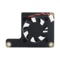
X680-A1

If you think it noisy, you can replace it with a C235 heatsink.
Packing List
- 1 x X680 4-port IP KVM Switch Kit
- 4 x USB2.0 A to B Cable (1.5m/59.06inch)
- 1 x DC 5V 4A Power Adapter (With US/EU Plug)
- 1 x Screws Pack
A note about this kit listing:
- 1. X630-A5 is only suitable for devices with ATX CONTROL such as desktops, servers, etc.
- 2. If you are using a device that supports ATX CONTROL, we recommend that you purchase X630-A5 and RJ45 ATX control cable kit;
- 3. X630-A5 is installed inside the ATX CONTROL device, one X630-A5 only supports one device; X680 supports simultaneous control of 4 devices
- 4. ATX CONTROL can support remote startup, shutdown, restart and other functions
- 5. You need to buy the appropriate length HDMI cable by yourself, because we don't know what length HDMI cable you need
- 6. The X680 Kits DO NOT include CM4 module also.
Additional accessories to purchase yourself:
- Raspberry Pi Compute Module 4 CM4
- A minimum 16 Gb class 10 memory card is recommended.(In fact, you don't need Micro SD card if you use CM4 with eMMC, because you can flash the firmware into the eMMC.)
ATX Conrol cable(Not included):
You can make your own ATX control cable, in fact, it is a normal Ethernet cable, and the requirements must be 568B line sequence

RJ45 Pinout of KVM:

Hardware Connection & installation
Refer to: https://youtu.be/ukHCz1RsFx4
X680 HDMI port display information, according to the test:

User Manual
PiKVM is a Free and Open Source Software that is released under the GPLv3 license. The Operating System (OS) image provided here is solely for the purpose of hardware testing. For commercial use, it is advised to directly contact the developers of PiKVM.
The development of this software would not be possible without the financial backing of the community. Contributions play a vital role in sustaining and advancing the project. If you wish to contribute, you can visit the PiKVM donation page at https://pikvm.org/donate/. Your support is greatly appreciated and will help in the continuous development and improvement of this software.
OS Download & Installation
1. Firstly, need prepair a micro sd card, a minimum 32/64 Gb class 10 memory card is recommended. If you use a CM4 with eMMC, you don't need a micro sd card.
2. Download an appropriate OS image for the PiKVM, the url link is https://pikvm.org/download/ or click this one to download it. (Please use the V3 Pre-Assembled OS image)
- We recommend that you use the 'V3 Pre-Assembled' version, and this image includes OLED display configuration.
- Only compatible with PiKVM V3 platform OS, NOT support PiKVM V4 Plus & V4 Mini platform!!!
Flash OS image
- 1. You can use Raspberry Pi Imager to Flash or the following alternatives tools:
- balenaEtcher: The application runs on Windows, MacOS, and Ubuntu operating systems.
- Win32 Disk Imager: This imaging software is designed for Windows machines.
- 2. Flash OS image to a microSD memory card by following the simple instructions or Official installation tutorial
- 3. Refer to #How to flash OS onto the eMMC of CM4? (CM4 with eMMC)? if you use the CM4 shield with eMMC.
- 4. Then power the device, then open explore to login the pikvm web ui.
- How to flash OS onto the eMMC of CM4? (CM4 with eMMC)?
- 1. Short nBOOT Pin, refer to the picture below.

- 2. Connect CM4 USB port with a Type-A to Type-B cable to your computer as follow:

- 3. Power the device via PWR DC Jack with 5V Power adaper
- 4. Then rerfer to this tutorial to flash raspberry pi OS
- 5. Remove the jumper of nBOOT after flashing is complete, then restart your device;
- PS:If you use CM4 with eMMC, then SD card cannot be used.
Configuring the PiKVM OS
- Login web UI
- Access to PiKVM Web Interface via any browser with the URL https://pikvm/ OR https://IP address of your ipkvm/, the default user and password is admin/admin
- Log into PiKVM and open Terminal program
- Switch to 'root' user
su root
- then type the password, and the default password is 'root' also.
- Switch OS to writable mode
rw
- Enable RTC (Only for X680 V1.3 because v1.3 use the ds1307 chip, Please skip this step if you X680 V1.5 using the same chip pcf8563 with pikvm official product)
- 1. Due to different RTC chips with official PiKVM hardware, you still need to configure RTC to make RTC work normally.
- 2. Insert the C1220 button battery. run the following command in web terminal window:
- 3. Edit the /boot/config.txt file, and change line
dtoverlay=i2c-rtc,pcf8563todtoverlay=i2c-rtc,ds1307(due to use the different RTC chip). sudo nano /boot/config.txt
- Then save & reboot the device;
- Test & setting RTC, write&read the time of Raspberry Pi to RTC DS1307
date
sudo hwclock -w
sudo hwclock -r
- Enable OLED display
- Run the following command in web terminal window to enable OLED display:
systemctl enable --now kvmd-oled kvmd-oled-reboot kvmd-oled-shutdown
- If you are using
PiKVM OS V3 Pre-Assembled, the OLED configuration is already pre-installed, you can ignore this step. - Rotate the OLED display by 180 degrees (Optional)
nano /usr/bin/kvmd-oled
- Change the line: return {"height": 64, "rotate": 2} to return {"height": 64, "rotate": 0}, then save & exit
- Enable pikvm hdmi audio
- Refer to Enable pikvm hdmi audio
- How to boot from NVME SSD?
- 1.Prepare the Win32 Disk Imager tool first, download and install it, refer to:https://sourceforge.net/projects/win32diskimager/
- 2. Insert NVME SSD into the USB to NVME ssd adapter or X876
- 3. Connect USB to NVME SSD adapter or X876 to computer through USB A cable, then a USB drive can be recognized in computer.
- 4. Open Win32 Disk Imager tool, then select the PiKVM os image file and USB drive, then click Write button
- 5. Wait a few minutes for the write process to complete.
- 6. Insert NMVE SSD into the X680, then power on (must remove the micro sd card firstly)
- Mass Storage Drive
- Refer to: https://docs.pikvm.org/msd/
- Check Video Output
ls /dev/video0
- Run the above command, if you see anything such as /dev/video0 other than file not found, then it’s available
- To support max resolution 1920x1080 60Hz (for V1.5 only)
nano /boot/config.txt
- Change the line7 from dtoverlay=tc358743 to dtoverlay=tc358743,4lane=1
- Save and exit by hitting CTRL + X, answering Y and hitting Enter when prompted.
- Editing the EDID
nano /etc/kvmd/tc358743-edid.hex
- Delete existing EDID data, then copy and paste below new EDID data
00FFFFFFFFFFFF005262888800888888
1C150103800000780AEE91A3544C9926
0F505400000001010101010101010101
010101010101011D007251D01E206E28
5500C48E2100001E8C0AD08A20E02D10
103E9600138E2100001E000000FC0054
6F73686962612D4832430A20000000FD
003B3D0F2E0F1E0A202020202020014F
020323454F041303021211012021A23C
3D3E1F102309070766030C00300080E3
007F8C8C0AD08A20E02D10103E9600C4
8E210000188C0AD08A20E02D10103E96
00138E210000188C0AA01451F0160026
7C4300138E2100009800000000000000
00000000000000000000000000000000
00000000000000000000000000000087
- Save and exit by hitting CTRL + X, answering Y and hitting Enter when prompted.
- Adding UI elements to control the KVM switch (for V1.5 only)
- Edit the file: /etc/kvmd/override.yaml and include the following:
kvmd:
    gpio:
        scheme:
            button1:
                pin: 16 # GPIO pin number for PC1
                mode: output
                switch: false
                pulse:
                    delay: 1
                    max_delay: 2
            button2:
                pin: 26 # GPIO pin number for PC2
                mode: output
                switch: false
                pulse:
                    delay: 1
                    max_delay: 2
            button3:
                pin: 11 # GPIO pin number for PC3
                mode: output
                switch: false
                pulse:
                    delay: 1
                    max_delay: 2
            button4:
                pin: 17 # GPIO pin number for PC4
                mode: output
                switch: false
                pulse:
                    delay: 1
                    max_delay: 2

        view:
            header:
                title: Switches  # The menu title
            table:  # The menu items are rendered in the form of a table of text labels and controls
                - ["#X680 IPKVM Switch"]  # Text starting with the sharp symbol will be a label
                - []  # creates a horizontal separator and starts a new table
                - ["#PC1-XXXXX:", button1]  # Text label for PC1, one button with text "Click"
                - ["#PC2-XXXXX:", button2]  # Text label for PC2, one button with text "Click"
                - ["#PC3-XXXXX:", button3]  # Text label for PC3, one button with text "Click"
                - ["#PC4-XXXXX:", button4]  # Text label for PC4, one button with text "Click"
- As follows

- Save and exit by hitting CTRL + X, answering Y and hitting Enter when prompted.
- Then restart the kvmd service with the coomand:
systemctl restart kvmd
- Disable writable mode
ro
- Reboot to make the changes take effect
reboot
- How to switch target computers/servers
- The IP KVM (X680) Switch supports direct switching through buttons on front panel and hotkey through keyboard connected to the special USB 1.1 port. it also supports remote hotkey switching between computers for easy monitoring.
- Computers/Servers Switching
- Press to select PC1/PC2/PC3/PC4 through buttons on front panel. the corresponding LED located on the right of the button will be on if a PC is selected. the PC1 will be automatically selected when power applied or restored.
- Hotkey switching
- Keyboard must be connected to USB1.1 port (Marked with an icon of keyboard)
- Press the "Ctrl" twice quickly, then immediately press "1" to switch to PC1
- Press the "Ctrl" twice quickly, then immediately press "2" to switch to PC2
- Press the "Ctrl" twice quickly, then immediately press "3" to switch to PC3
- Press the "Ctrl" twice quickly, then immediately press "4" to switch to PC4
- Remote hotkey switching
- Access to PiKVM web interface and log in
- Press the "Ctrl" twice quickly, then immediately press "1" to switch to PC1
- Press the "Ctrl" twice quickly, then immediately press "2" to switch to PC2
- Press the "Ctrl" twice quickly, then immediately press "3" to switch to PC3
- Press the "Ctrl" twice quickly, then immediately press "4" to switch to PC4
- If your mouse cursor is not in the area of the PiKVM web interface, it is not functional
- Switching hosts in the Web UI (for V1.5 only )
- To switch between hosts, enter the KVM UI and click the "Switches" menu. Click the buttons.

FAQ
- First of all, we recommend you to get more FAQ information on the official website: official FAQ, or check the following FAQ;
- You can post a issue ticket at Geekworm forum or email to us (support@geekworm.com) and attached your installation pictures or videos to get some help.
- Blog sharing for reference: https://www.andysblog.de/kvm-over-ip-pikvm-als-bausatz
Q: Why is the X680 not working?
A:
1. First you need to make sure your physical connection is correct, or you can email us at support@geekworm.com to confirm your physical connection;(Please make sure the CM4 is rightly and tightly connected.)
2. Make sure to use the right pikvm OS.

3. Make sure CM4 is tightly connected with X680. (This is very important, and this error often occurs)

Q: Why is USB mass driver not recognized?
A: Please refer to the description in the red rectangle in the picture below;

The USB mass is not recognized in PIKVM OS, you can understand USB mass as a local USB HUB in PIKVM OS.
These 3 USB ports are used for local switching between target PC1-PC4, e.g. a USB disk with the OS image can be used to install the os in PC1, if switching to PC2, then the os can be installed in PC2, and so on.
Q: How to switch to root user?
A: run the following command:
su root
Then type the password, the default password is 'root' also.
Q: Does the x680 support audio?
Q: Why OLED is not display?
A: Please follow the steps below to check
1. Please confirm that your OS is right:
Due to downloading the wrong firmware, the OLED cannot be displayed. We ALSO made such mistakes during testing
2. Please check if the order of OLED screen pins is correct, please email to support@geekworm.com if it's a wrong pin order;

The run the following command to check the I2C address
sudo i2cdetect -y 1
     0  1  2  3  4  5  6  7  8  9  a  b  c  d  e  f
00:                         -- -- -- -- -- -- -- --
10: -- -- -- -- -- -- -- -- -- -- -- -- -- -- -- --
20: -- -- -- -- -- -- -- -- -- -- -- -- -- -- -- --
30: -- -- -- -- -- -- -- -- -- -- -- -- 3c -- -- --
40: -- -- -- -- -- -- -- -- -- -- -- -- -- -- -- --
50: -- -- -- -- -- -- -- -- -- -- -- -- -- -- -- --
60: -- -- -- -- -- -- -- -- -- -- -- -- -- -- -- --
70: -- -- -- -- -- -- -- --
3c is a hexadecimal number, it is the I2C address of OLED, if you can’t find this value, please shut down and reconnect shield and OLED, then run this command again, If you still can't find the OLED's I2C address, the OLED screen may be damaged.
4. Then run the following command to enable OLED display:
rw
systemctl enable --now kvmd-oled
ro
Q: Does x680 support proarammable switch between PC?
A: NO
Q: Does the X680 support PoE power? How to enable PoE Power?
A: The X680 doesn't support POE, but you can use something similar to the PD3005G-3A
Q: Why can't I switch to another PC?'
A: You need to make sure that your target computer is not in sleep, because when the computer is sleep, the USB port will stop supplying power
Q: Why NVME SSD cannot be recognized?
A: Login the pikvm web teminal, then type the following command:
lspci
The result of the command should look similar to the following, if you can't find something similar to the following, your NVME SSD is not compatible
References
- ↑ PiKVM © belongs to https://pikvm.org
Enable comment auto-refresher
Anonymous user #3
Permalink |
Walker
Anonymous user #1
Permalink |
Anonymous user #2
Harry
Harry
Harry