X1012
Contents
Overview
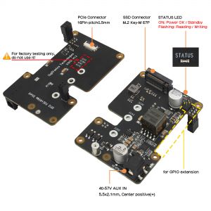
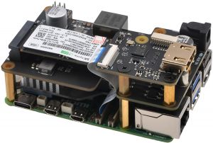
The X1012 NVMe+POE shield is specifically designed to offer a reliable power source and enhance storage capabilities for the Raspberry Pi 5.
POE (Power Over Ethernet) refers to the ability to provide DC power for IP-based network devices while transmitting data signals at the same time without affecting the standard Ethernet cabling infrastructure.
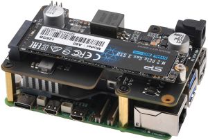
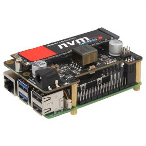
With its sleek and compact design, this shield allows for easy attachment of various M.2 SSD lengths (including 2280, 2260, 2242, and 2230) to your Raspberry Pi 5. It supports booting the operating system from your SSD, leading to quicker application launches, web serving, and file copying.
Important Notes
NVMe SSD Incompatibility List
We recommend avoiding the following NVMe SSD drives which is equipped with a Phison controller due to their proven incompatibility:
- WD Blue SN550 series (Solved! Refer to New rpi-eeprom-update 2024-01-24 WD Blue SN550 nvme works now.)
- WD Blue SN580 series
- WD Green SN350 series (Solved! Refer to NVMe_SSD_boot_with_the_Raspberry_Pi_5#comment-4602)
- WD Black SN850 series
- WD Black SN770
- WD SN740
- Inland tn446 nvme drive
- Corsair MP600 SSD
- Kingston NV3 NVME
- Micron 2450 SSD (Can be recognised but not support boot from NVME)
- Other NVMe SSD drivers equipped with the same Phison controller
These specific models have demonstrated compatibility issues, and it is advisable to avoid them when considering NVMe SSD options for the X10xx series NVMe shield. You can run "lspci" command to check the controller brand of the SSD.
We confirm that the following SSDs are incompatible:
- Micron 2200 256GB M.2 NVMe Gen3 x4, MODEL: MTFDHBA256TCH, The SSD is recognized but I cannot boot from it.
Also note:
- Compatible with M.2 NVMe SSDs only, Not compatible with M.2 SATA SSDs, M.2 PCIe AHCI SSDs, or other M.2 non-NVMe devices
- Older NVMe drives with less efficient flash media may not perform as well as newer drives
- New NVMe SSDs are not partitioned and will need to be both partitioned and formatted when first connected to the Raspberry Pi before they will be accessed in the Explorer.
- We get feedback from customers that Polaris Controller will also have compatibility problems. Please replace the other SSD test if it not work, whether it is compatible with the Raspberry Pi 5 does not depend on the X100X series boards
- NVMEs using the MAP1202 controller may not support PCIe Gen 2, and must be forced to enable PCIe Gen 3 in order to be recognised. This is due to the fact that the controller is not backward compatible with PCIe Gen 2, and NVMEs using this controller will have compatibility issues, and are not recommended for use. Can refer to https://zhuanlan.zhihu.com/p/644984347
PS: There is also feedback from buyers that even NVME SSDs with Phison controller are supported after updating the latest firmware. Please refer to go to: X1001#comment-4638
Features
| For use with |
Raspberry Pi 5 |
| Key Features |
POE
NVMe
|
| Technical Specification |
Power supply: 35-57VDC powering over Ethernet or 40-57Vdc via Auxiliary power jack[Power supply is selectable between the two; simultaneous power is not supported.] Ports & Connectors:
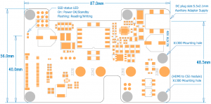
PCIe cable length: 30mm PCB Size: 87mm x 56mm |
Matching Case
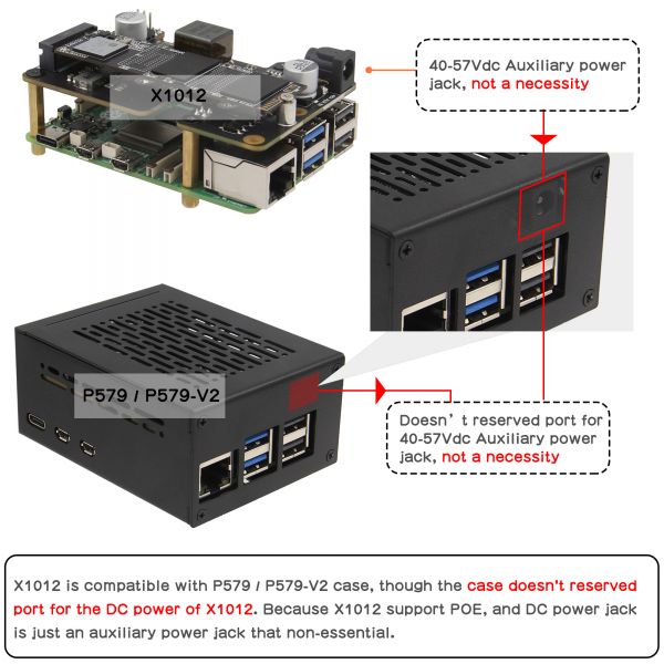
X1012 is compatible with P579-V2 case, though the case doesn't reserved port for the DC power of X1012. Because X1012 support POE, and DC jack is just an auxiliary power jack that non-essential.
User Manual
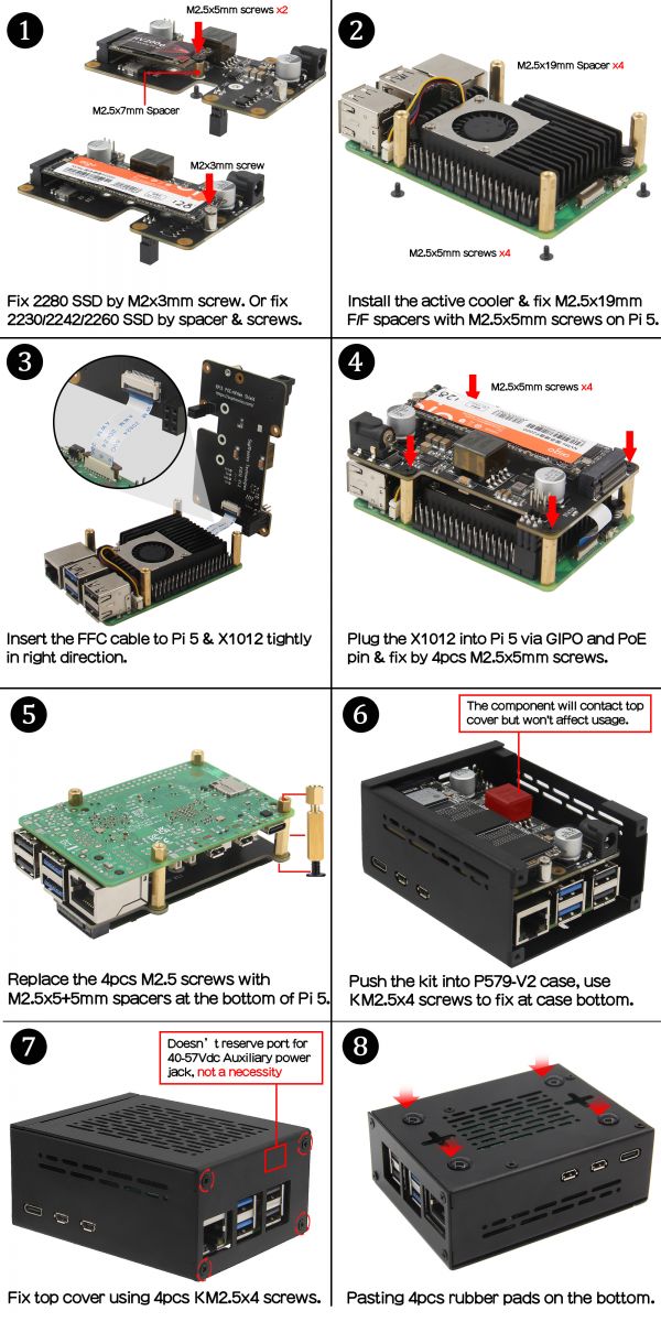
Hardware Installation
How to make it work
You need to do some configuration based on the current OS before the SSD can work, which is a basic requirement for RPi 5.
- Enable PCIe to make nvme ssd work, please refer to NVMe SSD boot with the Raspberry Pi 5
- Run the following command to tell the Pi that the X1012 POE is capable of 5A, so the USB current will get the full 1.6A
sudo rpi-eeprom-config -e
- Add
PSU_MAX_CURRENT=5000at the end of the file that reads like this:
- Press Ctrl-O, then enter, to write the change to the file.
- Press Ctrl-X to exit nano (the editor).
- Reboot your Raspberry Pi 5 to make the change take effect.
Introduction to Implementing Auxiliary Power on POE
- Introduction to Implementing Auxiliary Power on POE: File:AN3472-Implementing-Aux-Power-in-PoE.pdf
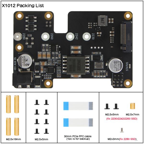
Packing List
- 1 x X1012 V1.2 NVMe with POE shield
- 2 x PCIe FFC (30mm length, Provides a backup)
- 10 x M2.5*5mm screws
- 4 x M2.5*19mm F/F Spacer
- 1 x M2.5* 7mm F/F Spacer (And two M2.5*5 screws to fix the 2230/2242/2260 SSDs)
- 1 x CM2x3mm screw (sliver color, to fix 2280 SSD only)
Test & Reviews
Test Conditions
- System board details: Raspberry Pi 5 Model B Rev 1.0 , 4G RAM
- Interface board details: X1012 POE+NVMe Shield
- Operation system: Raspberry Pi OS with desktop (Debian12 (bookworm), 64bit, Release date: October 10th 2023)
- Storage details: Netac N930E-PRO M.2 NVMe 128GB
Testing the SSD speed from command line with dd
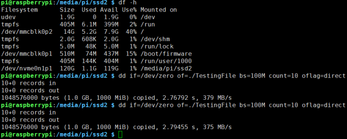
- To test the write speed, writing 1 GB of data in 10 blocks of 100 MB.
- To test the read speed, use dd to read our entire TestingFile file generated from the last command, in 10 blocks of 100 MB each.
Run at PCIe 2.0
Run at PCIe 3.0
As seen above, the final results with the dd command are:
- Write speed: 389 MB/s at PCIe 2.0, 377MB/s at PCIe 2.0
- Read speed: 730 MB/s at PCie 2.0, 700MB/s at PCIe 3.0
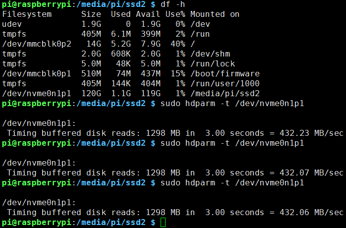
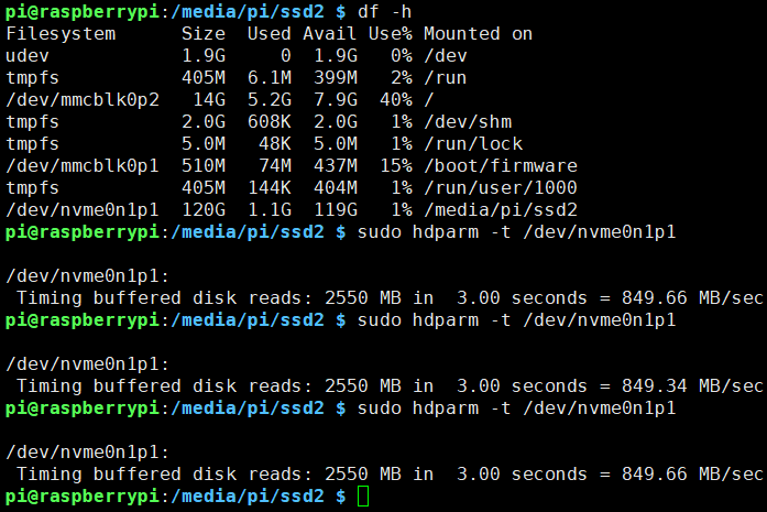
Testing disk drive read speed with hdparm
Run at PCIe 2.0, average read rate: 432 MB/s (3 samples)
Run at PCIe 3.0, average read rate: 849.5 MB/s (3 samples)


Enable comment auto-refresher
Anonymous user #7
Permalink |
Lisa
Anonymous user #6
Permalink |
Lisa
Anonymous user #5
Permalink |
Lisa
Anonymous user #4
Permalink |
Anonymous user #3
Permalink |
Lisa
Anonymous user #3
Lisa
Anonymous user #2
Permalink |
Lisa
Anonymous user #1
Permalink |
Lisa