Contents
Overview
NASPi CM4-M2 is a member of NASPi family. Click GEEKWORM NAS Family to know more.
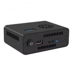
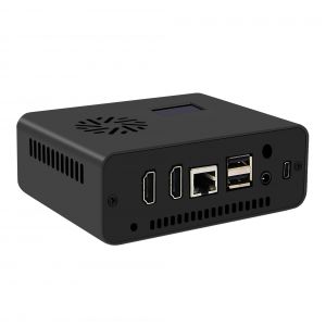
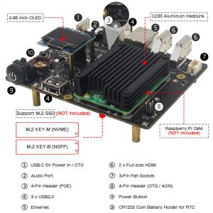
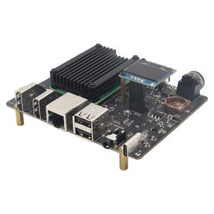
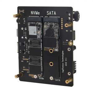
NASPi CM4-M2 is a NUC-style storage kit based on Raspberry Pi CM4 all series. It has a M2 KEY-M (NVME) SSD interface and a M2 KEY-B (NGFF) SSD interface. Its OLED screen can display some informations like CPU temperature, IP address . Also provides 3 USB 2.0 ports and 2 full-size HDMI ports, supports safe shutdown (requires installation script).
Important note:
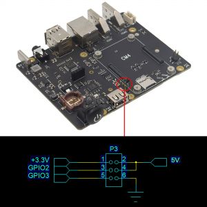
- Don't need to use additional SD card and power supply if you are using CM4 with emmc. When burning the system, please short the OTG on the X515 board; at the same time, use the USB-A to USB-C OTG cable (prepare it yourself) to connect to the computer.
Features
- Model: NASPi CM4-M2
- NUC style set-top box, compact design
- Compatible with M2 NVME SSD or M2 SATA SSD(Only support 2280 length SSD installation)
- Comes with an aluminum alloy heatsink C235 for CM4 passive cooling
- Comes with a 0.96 inch OLED display
- Support software safe shutdown & auto power on & RTC function
- On-board blue light button switch to control power ON/OFF
- Press button switch to turn on, hold for 1~2 seconds to reboot, hold for 3 seconds to safe shutdown, hold for more than 8 seconds to force shutdown
How to Power
Power supply: 5Vdc +/-5% , ≥4A
Recommend to use 20W 5V 4A Type-C power adapter PSU20.
How to Cool
- Comes with a 12mm thickness aluminum alloy heatsink C235 cooler for passive cooling of Raspberry Pi CM4, which can satisfy large file copy and video playback application. And it is recommended to replace the thermal pad with CPU silicone grease for better heat dissipation.
Packing List
- 1 x NASPi CM4-M2 aluminum alloy case
- 1 x X515 storage expansion board
- 1 x C235 aluminum alloy heatsink
- 1 x 0.96 inch OLED display
- 1 x Scews pack accessories
Additional accessories to purchase yourself:
- Raspberry Pi Compute Module 4 CM4
- A minimum 16 Gb class 10 memory card is recommended.(In fact, you don't need Micro SD card if you use CM4 with eMMC, because you can flash the firmware into the eMMC.)
User Manual
Installation Video
For NASPi CM4-2.5 and NASPi CM4-M2: https://youtu.be/lXBK5-GFQ48
Please follow the steps below
Flash OS Image
Due to CM4 has a version with eMMC, micro SD card is optional. If you are using the CM4 with eMMC, you don't need to buy a extra Micro SD card.
You flash the OS image into different media according to your own situation.
1. Flash OS into the micro SD card
- A minimum 16 Gb class 10 memory card is recommended.
- Please refer to Official installation tutorial
2. Flash OS into the eMMC of CM4(Optional)
- You can falsh OS into the eMMC if you use the CM4 with eMMC, refer to the following step.
- 1. Short OTG Pin, refer to the picture below.
- 2. Connect a computer that will be used to load the eMMC to the USB C port on the CM4-M2 board. The computer will provide both power and data to the CM4. (Type-A to Type-C OTG cable need to be purchased seperately)
- 3. Then rerfer to this tutorial to flash raspberry pi OS
- 4. Remove the jumper of OTG after flashing is complete, then restart your device;
- PS:If you use CM4 with eMMC, then SD card cannot be used.
3. Preconfigure Device for CM4
Now we think you have successfully flashed the OS to the storage media (mciro sd card or eMMC of CM4). If you attempt to boot now you will not have working USB ports, ssh, or any wireless configuration, so do not remove your SD card, proceed as follows.
We can preconfigure your CM4 device by plugging mico sd via sd reader into a windows computer / Pi. You should see the “boot” volume where we can preconfigure our CM4 to be working right from the start.
3.1 Enable USB Ports
- When mounted in the IO board the USB ports will not function without making a change to config.txt and adding an overlay.
- Add the following line to config.txt:
dtoverlay=dwc2,dr_mode=host
- After adding this line the two USB ports (as well as the “External USB” header) will function the next time the CM4 boots.
3.2 Enable SSH
- It's very useful to have SSH enabled when working with the Compute Module 4. It is enabled simply by creating an empty file named:
touch ssh
- in the root folder of the “boot” volume (the top-most folder of the drive where start4x.elf, fixup.dat and those files are located)
- Now when the Pi starts up SSH will automatically be enabled!
- PS: This step is optional, you can also enable ssh through the
raspi-configprogram after the device boot
3.3 Preconfigure WiFi / Wireless (Optional)
- You can also preconfigure the Compute Module 4 (and any Pi) by creating wpa-supplicant.conf at the base of the “boot” volume like we did with “ssh” file. In fact, you can setup your wifi after you boot up.
- Create a new file named wpa-supplicant.conf that contains the following:
ctrl_interface=DIR=/var/run/wpa_supplicant GROUP=netdev
country=US
update_config=1

network={
 ssid="YourNetwork"
 psk="YourPassword"
}
When this file is created in the base of the “boot” volume it will automatically be applied to the Pi upon the next startup. Make sure to adjust your country=US line to your own country as this can impact what channels and functionality are available from your WiFi card!
Then you can insert your micro sd card into the device & power on it.
4. Installing script
After the device is reboot, install the following script to get safe and software shutdown function: refer to XScript
5. Enable OLED display
Refer to How to enable OLED display
6. Flash OS into the NVME SSD(Optional)
Load OS into ssd and you can get extremely fast running speed, you need to refer to the above steps to flash the OS into the Micro SD card firstly, then insrt the Micro sd card, turn on the device, and then click Applications =>Accessories =>SD Card Copier, run the SD Card Copier program, and copy the OS to the ssd as shown in the figure below.
Click Start to run. Then shut down, unplug the SD card, and restart the device.
FAQ
Q: How to enable the POE option?
A. The POE header on X515/X510 is reserved to be compatible with the official POE+ HAT. But we don't know if the case will be compatible with the installation of official POE+ HAT.
Video
Thanks for the video from leepspvideo! https://youtu.be/tgSNGbbFk1c

Enable comment auto-refresher
Anonymous user #8
Permalink |
Anonymous user #9
Anonymous user #7
Permalink |
Lisa
Anonymous user #6
Permalink |
Anonymous user #6
Anonymous user #6
Walker
Anonymous user #5
Permalink |
Walker
Anonymous user #4
Permalink |
Walker
Anonymous user #3
Permalink |
Walker
Anonymous user #2
Permalink |
Harry
Anonymous user #1
Permalink |
Anonymous user #1
Abby