CM4 to CM3 Adapter

From Geekworm Wiki
Revision as of 11:22, 30 September 2021 by Cindy (talk | contribs)
(diff) ← Older revision | Latest revision (diff) | Newer revision → (diff)
Jump to navigation Jump to search

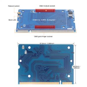
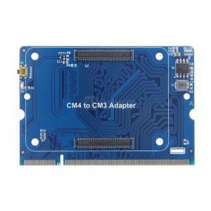
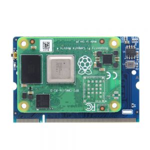
CM4 to CM3 Adapter-Front
CM4 to CM3 Adapter-Back
CM4 to CM3 Adapter-Installation Directions
CM4 to CM3 Adapter-Interface&Dimensions
Interface definition diagram

Overview

Since the Raspberry Pi Compute Module 3 (CM3) module is in short supply, the CM4 to CM3 adapter is designed to convert CM4 module to CM3 interface.

This adapter board converts the latest Raspberry Pi Compute Module 4 (CM4) to CM3 interface, allowing CM4 to adapt to the old CM3+/CM3/CM3L series baseboard. Also Support to use CM4 with Geekworm 12mm aluminum alloy heatsink C235.

When install the CM4 module into CM4 to CM3 adapter board, please pay attention to the CM4 install directions.

Note:

  1. Make sure that the CM4 module is installed on the expansion board correctly before power on.
  2. Please pay attention to the CM4 install directions.
  3. The Raspberry Pi Compute Module 4 or heatsink is not included in the packing list.

Features

  • Raspberry Pi Compute Module 4 interface
  • 1 x CM3 interface
  • 1 x Boot led(System status led indicator)
  • 1 x Reboot Button
  • Operating temperature: 0℃~80℃
  • Dimensions: 67.6x46.5mm/2.66x1.83inch

User Manual

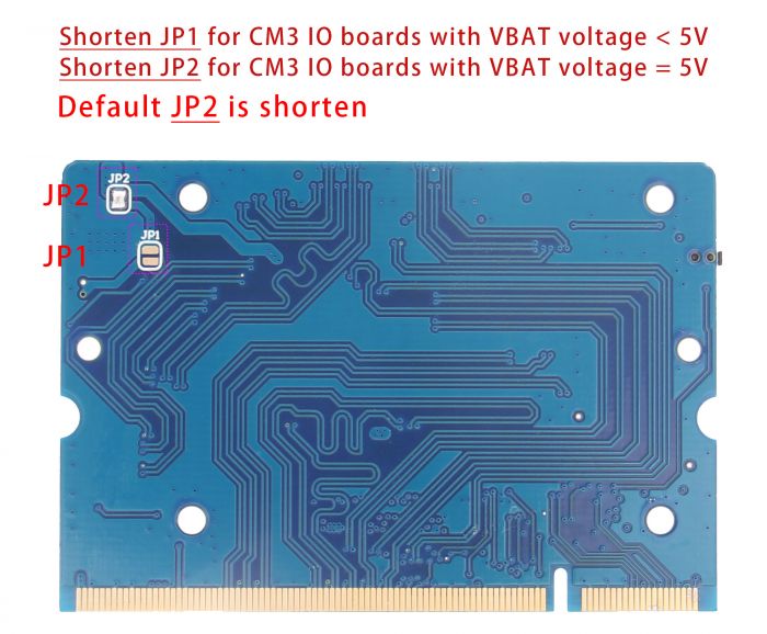
Why have JP1 & JP2?

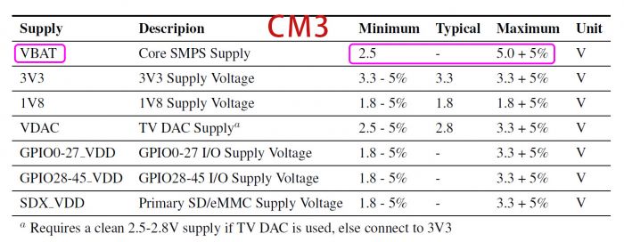
The VBAT voltage range of CM3 is 2.5-5V, and the VBAT voltage of most CM3 IO boards is 3.3V or 5V, but the VBA voltage of CM4 is only 5V. When the VBAT of the CM3 IO board used is 3.3V, a DC circuit is needed; but if the VBAT of the CM3 IO board is 5V, the DC voltage will produce howling because it does not need to be boosted;

Please shorten JP1 only for CM3 IO board with VBAT voltage less than 5V, or shorten JP2 only for CM3 IO board with VBAT volgate of 5V;

CM4 to CM3 adapter CM3 VBAT voltage

But this issue has been solved in the current production batch.

Packing List

1x CM4 to CM3 Adapter

FAQ

Q1:Which GPIO can be used after use the CM4 to CM3 Adapter?

A: CM3 has 46 GPIOs, ranging from GPIO0~GPIO45; while CM4 has only 28 GPIOs, ranging from GPIO0~GPIO27; so if you want to use CM4 to replace CM3, GPIO can only use GPIO0~GPIO27, because CM4 has only 28 GPIO, please refer to the datasheet of CM4 and CM3, thanks!

Q2: Does the CM4 to CM3 Adapter support CM4 Lite?

A: Yes, you can use the CM4 to CM3 Adapter covert CM4 Lite to CM3 Lite. But please make sure your CM3 IO board is support the CM3 Lite, then you can use it.

Add your comment
Geekworm Wiki welcomes all comments. If you do not want to be anonymous, register or log in. It is free.


Anonymous user #8

25 months ago
Score 0++

Hi, i have a problem with de CM4 to CM3 adaptor . I have a CM3 evaluation board with CM3 -> HDMI works ok. CM3 evaluation board with a CM4 to CM3 adaptor and a CM4 then i have only 3 seconds HDMI signal when CM4 boot. ( Raspberry logo ) ( CM4 is running only no HDMI signal)

Same CM4 on a compute module 4 IO board HDMI ok.

Lisa

25 months ago
Score 0++

Hello,

The Raspberry PI logo shows that it can be displayed. There should be a configuration problem.


CM3 has only one video output interface, while Raspberry PI CM4 has two output interfaces. There should be a problem with the configuration of the system desktop display. Please check the configuration.


Or try reinstalling with the official system to test it out.

Anonymous user #7

26 months ago
Score 0++
Hi,is your adapter RoHS compliant?

Anonymous user #6

31 months ago
Score 0++
Hi, trying to connect the official 7-inch LCD. The LCD is set up using I2C on pin3 and pin5 on the CM3, but you have GPIO0 and GPIO1 connected to these pins. According to the CM4 datasheet, there are no GPIO0 nor GPIO1... 2 Questions: 1) Is the I2C connected? If yes, where? 2) To which pins on the CM4 are pin3 and pin5 on the SODIMM connector connected to?

Lisa

31 months ago
Score 0++

Hi,please refer the picture[Interface definition diagram];

CM4 has gpio0,gpio1;

ID_SD of CM4 corresponds to GPIO0, ID_SC is GPIO1

Anonymous user #5

31 months ago
Score 0++
Would this work with the CM4 Lite? (No eMMC)

Anonymous user #5

31 months ago
Score 0++
It does work with the CM4.

Lisa

31 months ago
Score 0++

Hi,

Please refer CM4 to CM3 Adapter#FAQQ2

Anonymous user #4

35 months ago
Score 0++
I am having trouble using a USB port tied to pins 165 and 167 on the CM3 connector. Does anyone know if pins 165 and 167 are directly connected to CM4 pins 103 and 105 (USB N & P)? Also, I noticed that pin 168 on the CM3 connector does not mention a USB_OTG_ID pin. Does this board not support mulitple USB ports? Thank you.

Lisa

35 months ago
Score 0++

Hello,

The USB interface is disabled to save power by default on the CM4 . To enable it you need to add dtoverlay=dwc2,dr_mode=host to the config.txt file, detail to refer to CM4 datasheet. please refer CM4 Stick

Anonymous user #4

35 months ago
Score 0++
Lisa, I had already added that line to the config.txt. My CM4 seemed to work fine with a CM4 I/O board USB connection, but I am not getting any USB signal from the CM4 to CM3 adapter on a CM3 board. The boot light is flashing, so it seems to be loading the image off of the SD card, but I am not getting USB signal. Is there a full pinout diagram for the CM4 to CM3 adapter that shows the CM4 connections? Thank you.

Lisa

35 months ago
Score 0++
Hi,please refer the 【Interface definition diagram】on the right

Anonymous user #3

38 months ago
Score 0++
dtoverlay=dwc2,dr_mode=host was necessary to make the USB bus work on the CM4 IO Board. I am having problems with the USB bus through the converter with a VBAT of 3.3V for the converter. The USB breakout is getting 5V and was working properly with a CM3+. Any ideas on troubleshooting?

Anonymous user #3

38 months ago
Score 0++
The CM4 was not seated all the way in the converter. We also needed to use a USB hub to reduce the strain on the 3.3 V bus on our custom board but then it seemed to work.

Anonymous user #2

38 months ago
Score 0++
Anonymous User #2 is GBX Technology, Giancarlo Bregante.

Lisa

38 months ago
Score 0++

Hi,

CM4 does not have gpio44 and gpio45, so only csi0 can be used.

Anonymous user #2

38 months ago
Score 0++

We are using both MIPI CSI Cameras (0 and 1) on the actual CM3 design so two I2C interfaces needs to be used. We found GPIO0 and GPIO (I2C0) for Camera 0 are connected from CM4 to CM3 and Camera 0 works OK. Camera 1 is NOT working, so please let me know if GPIO44 and GPIO45 (I2C) for Camera 1 are connected/mapped from CM4 to CM3. Waiting for your answer immediately.

Thanks.

Anonymous user #1

39 months ago
Score 0++
ETA1096 buzzing when installed in an Allo USBridge Signature

Lisa

39 months ago
Score 0++
Hello,Could you please provide us with some test pictures and videos for reference? please send to support@geekworm.com ;and please tell us your order number,Thanks!

Lisa

39 months ago
Score 0++
This may be because the inductance of the power supply you are using produces a common frequency. We recommend that you replace a charger. We have responded to your question via email, please confirm the email.thanks