Difference between revisions of "X728-hardware"
| (71 intermediate revisions by 3 users not shown) | |||
| Line 1: | Line 1: | ||
| + | |||
{{GD Template Impl}} | {{GD Template Impl}} | ||
| − | Power Jack and Connectors | + | ==Overview== |
| + | '''X728 V2.5''' | ||
| + | |||
| + | [[File:IMG-0449-interface-EN.jpg|800px|X728 V2.5]] | ||
| + | |||
| + | '''X728 V2.3''' | ||
| + | |||
| + | [[File:X728-V2.3-Interface-EN.jpg|800px|X728 V2.3]] | ||
| + | |||
| + | [[File:X728-V2.3-Jumper-cap-function.jpg|800px|X728 V2.3]] | ||
| + | |||
| + | '''X728 V2.1''' | ||
| + | |||
| + | [[File:X728-V2.1-interface-EN.jpg|X728 V2.1 Interface]] | ||
| + | |||
| + | Update: | ||
| + | *New add a buzzer controled by GPIO20 | ||
| + | *DC jack is changed from DC5525 to DC5521. | ||
| + | |||
| + | '''X728 V2.0''' | ||
| + | |||
| + | [[File:X728-V2.0-01.jpg|700px|none|X728 V2.0]][[File:X728-V2.0-02.jpg|700px|none|X728 V2.0]] | ||
| + | |||
| + | Update: | ||
| + | * PIN33 (GPIO13) is replaced by the PIN37 (GPIO26) to avoid the I2S interface from v1.3 to v2.0. | ||
| + | |||
| + | '''X728 V1.3''' | ||
| + | |||
| + | [[File:X728-V1.3-Interface.jpg|800px|X728-V1.3-Interface]] | ||
| + | |||
| + | '''X728 V1.2''' | ||
| + | |||
| + | [[File:X728-IMG-7960-1.jpg|800px]] | ||
| + | |||
| + | [[File:X728-IMG-7979-1.jpg|800px]] | ||
| + | |||
| + | ==Power Jack and Connectors== | ||
{| class="wikitable collapsible collapsed" | {| class="wikitable collapsible collapsed" | ||
| Power input || 5Vdc +/- 5% ,≥3A | | Power input || 5Vdc +/- 5% ,≥3A | ||
| Line 12: | Line 49: | ||
| Power output connector || XH2.54mm 2pin | | Power output connector || XH2.54mm 2pin | ||
|} | |} | ||
| − | == | + | |
| + | # X728 powers the Raspberry Pi via the 40-pin header (Pin 2 & 4) | ||
| + | # Don't power the Raspberry Pi via the Pi's type-C USB socket | ||
| + | # X728 can be powered via the onboard DC jack <span style="color:red;">or</span> Type-C USB power socket | ||
| + | ==Pins and GPIO used== | ||
| + | <span style="color:red;">PIN33 (GPIO13) is replaced by the PIN37 (GPIO26) to avoid the I2S interface from v1.3 to v2.0.</span> | ||
| + | |||
| + | {| class="wikitable collapsible collapsed" | ||
| + | ! Pin No. !! Usage | ||
| + | |- | ||
| + | | 2, 4 || +5V power supply | ||
| + | |- | ||
| + | | 3, 5 || I2C for RTC and battery fuel-gauge systems | ||
| + | |- | ||
| + | | 6 || Ground | ||
| + | |- | ||
| + | | 29 || GPIO5 for power management | ||
| + | |- | ||
| + | | 32 || GPIO12 for power management | ||
| + | |- | ||
| + | | 33 || GPIO13 for power management <span style="color:red;">(For V1.3 and previous versions only)</span> | ||
| + | |- | ||
| + | | 31 || GPIO6 for AC power loss detection (PLD jumper inserted, High=Power loss,Low=Power supply normal) | ||
| + | |- | ||
| + | | 37 || GPIO26 for power management <span style="color:red;">(New add from V2.0)</span> | ||
| + | |- | ||
| + | | 38 || GPIO20 for buzzer control <span style="color:red;">(New add from V2.1 )</span> | ||
| + | |- | ||
| + | | 36 || GPIO16 for battery charging control <span style="color:red;">(New add from V2.5 )</span> | ||
| + | |} | ||
| + | |||
| + | |||
| + | {| class="wikitable" | ||
| + | ! Pin No. !! GPIO No. !! Remark !! Ver 1.2 !! Ver 1.3 !! Ver 2.0 !! Ver 2.1 !! Ver 2.2 !! Ver 2.3!! Ver 2.5 | ||
| + | |- | ||
| + | | 2, 4 || || 5V || √ || √ || √ || √ || √ || √||√ | ||
| + | |- | ||
| + | | 3, 5 || || I2C for RTC and battery fuel-gauge systems || √ || √ || √ || √ || √ || √||√ | ||
| + | |- | ||
| + | | 6 || || Ground || √ || √ || √ || √ || √ || √||√ | ||
| + | |- | ||
| + | | 29 || GPIO05 || Power management || √ || √ || √ || √ || √ || √||√ | ||
| + | |- | ||
| + | | 31 || GPIO06 || for AC power loss detection<br>(PLD jumper inserted, <br>High=Power loss,Low=Power supply normal) || √ || √ || √ || √ || √ || √||√ | ||
| + | |- | ||
| + | | 32 || GPIO12 || Power management || √ || √ || √ || √ || √ || √||√ | ||
| + | |- | ||
| + | | 33 || GPIO13 || Power management || √ || √ || || || || || | ||
| + | |- | ||
| + | | 37 || GPIO26 || Power management<br>GPIO13 is replaced to GPIO26 from Ver 2.0 || || || √ || √ || √ || √||√ | ||
| + | |- | ||
| + | | 38 || GPIO20 || for Buzzer control || || || || √ || √ || √||√ | ||
| + | |- | ||
| + | | 36 || GPIO16 || for battery chargingcontrol || || || || || || ||√ | ||
| + | |} | ||
| + | |||
| + | ==6-Pin Function Header for X728 V1.2== | ||
| + | {| class="wikitable collapsible collapsed" | ||
| + | ! Jumper Name !! Usage | ||
| + | |- | ||
| + | | PLD | ||
| + | (Power loss detection)" | ||
| + | || Short - AC Power loss or power adapter failure detection enabled | ||
| + | <span style="color:red;">(Active if power adapter disconnected)</span> | ||
| + | Open - Power loss detection disabled | ||
| + | |- | ||
| + | | AON | ||
| + | (Auto power-on) | ||
| + | || Short - Auto power-on when power applied | ||
| + | <span style="color:red;">(Will delay 3 seconds before powering on)</span> | ||
| + | Open - Auto power-on disabled | ||
| + | |- | ||
| + | | ASD | ||
| + | (Auto shutdown) | ||
| + | || Short - Automatic shutdown enabled when battery low (≤3Vdc ) | ||
| + | <span style="color:red;">(Battery must be >3V and installed before enabling this function)</span> | ||
| + | Open - Automatic shutdown disabled | ||
| + | |||
| + | Procedure to enable ASD function --IMPORTANT | ||
| + | 1. Battery voltage must be >3Vdc | ||
| + | 2. Insert the battery into the holder | ||
| + | 3. Wait 3 seconds then insert the jumper | ||
| + | 4. If the jumper inserted before battery, remove | ||
| + | battery & jumper then repeat step 1, 2 and 3. | ||
| + | |} | ||
| + | |||
| + | ==Connector for External Power Switch== | ||
| + | {| class="wikitable collapsible collapsed" | ||
| + | ! Pin No. !! Pin Description | ||
| + | |- | ||
| + | | 1 || Power on/off control connecting to switch | ||
| + | |- | ||
| + | | 2 || Ground | ||
| + | |- | ||
| + | | 3 || Ground | ||
| + | |- | ||
| + | | 4 || LED+ for power on, rebooting and shutdown | ||
| + | |} | ||
| + | |||
| + | # Please use <span style="color:red;">momentary</span> switch only and don't use latching switch | ||
| + | # Connector - Pitch 2.0mm 4pos | ||
| + | |||
| + | ==Power button (Script for power mgnt installed)== | ||
| + | {| class="wikitable collapsible collapsed" | ||
| + | | Press and Release || Raspberry Pi and X728 turn on | ||
| + | |- | ||
| + | | Press and hold for 1~2 seconds || System rebooting | ||
| + | |- | ||
| + | | Press and hold for 3~7 seconds || System shutting down | ||
| + | |- | ||
| + | | Press and hold for >8 seconds || Force shutdown | ||
| + | |} | ||
| + | |||
| + | ==Function LEDs== | ||
| + | {| class="wikitable collapsible collapsed" | ||
| + | ! LED Name !! Usage | ||
| + | |- | ||
| + | | BAT LOW || LED red on indicates battery low (≤3.0Vdc) or blue power button pressed (Jumper for ASD inserted) | ||
| + | |- | ||
| + | | || | ||
| + | |- | ||
| + | | 5V OUT || LED green on flashing indicates 5V power out and UPS powered by battery | ||
| + | |- | ||
| + | | AC FAIL || LED red on indicates AC power loss or PSU failure or PSU disconnected | ||
| + | |- | ||
| + | | || | ||
| + | |- | ||
| + | | PWR || LED blue indicates | ||
| + | Stays on - Power on | ||
| + | Blinks rapidly - system rebooting | ||
| + | Blinks slowly - Shutting down | ||
| + | |} | ||
| + | |||
| + | ==Fuel gauge - LED Indicator== | ||
| + | <span style="color:red;">Operation of Discharging:</span> | ||
| + | {| class="wikitable collapsible collapsed" | ||
| + | ! Capacity C (%) !! D1 !! D2 !! D3 !! D4 | ||
| + | |- | ||
| + | | C ≥75% || ON || ON || ON || ON | ||
| + | |- | ||
| + | | 50%≤C<75% || ON || ON || ON || OFF | ||
| + | |- | ||
| + | | 25%≤C<50% || ON || ON || OFF || OFF | ||
| + | |- | ||
| + | | 3%≤C<25% || ON || OFF || OFF || OFF | ||
| + | |- | ||
| + | | 0%<C<3% || Flashing || OFF || OFF || OFF | ||
| + | |} | ||
| + | |||
| + | <span style="color:red;">Operation of charging:</span> | ||
| + | {| class="wikitable collapsible collapsed" | ||
| + | ! Capacity C (%) !! D1 !! D2 !! D3 !! D4 | ||
| + | |- | ||
| + | | Fully charged || ON || ON || ON || ON | ||
| + | |- | ||
| + | | 75%≤C || ON || ON || ON || Flashing | ||
| + | |- | ||
| + | | 50%≤C<75% || ON || ON || Flashing || OFF | ||
| + | |- | ||
| + | | 25%≤C<50% || ON || Flashing || OFF || OFF | ||
| + | |- | ||
| + | | C<25% || Flashing || OFF || OFF || OFF | ||
| + | |} | ||
| + | |||
| + | ==PCB Layout== | ||
| + | <gallery> | ||
| + | X728-PCB.png|X728 V1.3 PCB Layout | ||
| + | X728_V2.0_PCB_Layout.jpg|X728 V2.0 PCB Layout | ||
| + | X728-V2.1-PCB.png|X728 V2.1 PCB Layout | ||
| + | </gallery> | ||
| + | |||
| + | ==18650 battery dimension== | ||
| + | [[File:18650size.png]] | ||
| + | <span style="color:red;">Do not use 18650 battery with built-in protection circuit</span> | ||
| + | |||
| + | ==Raspberry Pi Official GPIO Expansion describe== | ||
| + | [[File:RPI-GPIO-expansion.png | 800px]] | ||
| + | |||
| + | ==Installation Guide== | ||
| + | Installation Video for X728+X728-A1+X728-A2: https://youtu.be/q_TmqMNhJPM | ||
| + | |||
| + | {{#ev:youtube|https://youtu.be/q_TmqMNhJPM}} | ||
| + | |||
| + | [[File:X728+X728A1+X728A2-Installation-Guide.jpg|800px|X728]] | ||
| + | |||
| + | Return to [[X728]] | ||
<!--Add review function! --> | <!--Add review function! --> | ||
Latest revision as of 16:47, 1 August 2023
Contents
- 1 Overview
- 2 Power Jack and Connectors
- 3 Pins and GPIO used
- 4 6-Pin Function Header for X728 V1.2
- 5 Connector for External Power Switch
- 6 Power button (Script for power mgnt installed)
- 7 Function LEDs
- 8 Fuel gauge - LED Indicator
- 9 PCB Layout
- 10 18650 battery dimension
- 11 Raspberry Pi Official GPIO Expansion describe
- 12 Installation Guide
Overview
X728 V2.5

X728 V2.3


X728 V2.1

Update:
- New add a buzzer controled by GPIO20
- DC jack is changed from DC5525 to DC5521.
X728 V2.0


Update:
- PIN33 (GPIO13) is replaced by the PIN37 (GPIO26) to avoid the I2S interface from v1.3 to v2.0.
X728 V1.3

X728 V1.2


Power Jack and Connectors
| Power input | 5Vdc +/- 5% ,≥3A |
| DC Power Plug Size | 5.5*2.5mm |
| USB power in socket | Type-C |
| UPS power output | 5.1Vdc 8A |
| Power output connector | XH2.54mm 2pin |
- X728 powers the Raspberry Pi via the 40-pin header (Pin 2 & 4)
- Don't power the Raspberry Pi via the Pi's type-C USB socket
- X728 can be powered via the onboard DC jack or Type-C USB power socket
Pins and GPIO used
PIN33 (GPIO13) is replaced by the PIN37 (GPIO26) to avoid the I2S interface from v1.3 to v2.0.
| Pin No. | Usage |
|---|---|
| 2, 4 | +5V power supply |
| 3, 5 | I2C for RTC and battery fuel-gauge systems |
| 6 | Ground |
| 29 | GPIO5 for power management |
| 32 | GPIO12 for power management |
| 33 | GPIO13 for power management (For V1.3 and previous versions only) |
| 31 | GPIO6 for AC power loss detection (PLD jumper inserted, High=Power loss,Low=Power supply normal) |
| 37 | GPIO26 for power management (New add from V2.0) |
| 38 | GPIO20 for buzzer control (New add from V2.1 ) |
| 36 | GPIO16 for battery charging control (New add from V2.5 ) |
| Pin No. | GPIO No. | Remark | Ver 1.2 | Ver 1.3 | Ver 2.0 | Ver 2.1 | Ver 2.2 | Ver 2.3 | Ver 2.5 |
|---|---|---|---|---|---|---|---|---|---|
| 2, 4 | 5V | √ | √ | √ | √ | √ | √ | √ | |
| 3, 5 | I2C for RTC and battery fuel-gauge systems | √ | √ | √ | √ | √ | √ | √ | |
| 6 | Ground | √ | √ | √ | √ | √ | √ | √ | |
| 29 | GPIO05 | Power management | √ | √ | √ | √ | √ | √ | √ |
| 31 | GPIO06 | for AC power loss detection (PLD jumper inserted, High=Power loss,Low=Power supply normal) |
√ | √ | √ | √ | √ | √ | √ |
| 32 | GPIO12 | Power management | √ | √ | √ | √ | √ | √ | √ |
| 33 | GPIO13 | Power management | √ | √ | |||||
| 37 | GPIO26 | Power management GPIO13 is replaced to GPIO26 from Ver 2.0 |
√ | √ | √ | √ | √ | ||
| 38 | GPIO20 | for Buzzer control | √ | √ | √ | √ | |||
| 36 | GPIO16 | for battery chargingcontrol | √ |
6-Pin Function Header for X728 V1.2
| Jumper Name | Usage |
|---|---|
| PLD
(Power loss detection)" |
Short - AC Power loss or power adapter failure detection enabled
(Active if power adapter disconnected) Open - Power loss detection disabled |
| AON
(Auto power-on) |
Short - Auto power-on when power applied
(Will delay 3 seconds before powering on) Open - Auto power-on disabled |
| ASD
(Auto shutdown) |
Short - Automatic shutdown enabled when battery low (≤3Vdc )
(Battery must be >3V and installed before enabling this function) Open - Automatic shutdown disabled Procedure to enable ASD function --IMPORTANT 1. Battery voltage must be >3Vdc
2. Insert the battery into the holder
3. Wait 3 seconds then insert the jumper
4. If the jumper inserted before battery, remove
battery & jumper then repeat step 1, 2 and 3.
|
Connector for External Power Switch
| Pin No. | Pin Description |
|---|---|
| 1 | Power on/off control connecting to switch |
| 2 | Ground |
| 3 | Ground |
| 4 | LED+ for power on, rebooting and shutdown |
- Please use momentary switch only and don't use latching switch
- Connector - Pitch 2.0mm 4pos
Power button (Script for power mgnt installed)
| Press and Release | Raspberry Pi and X728 turn on |
| Press and hold for 1~2 seconds | System rebooting |
| Press and hold for 3~7 seconds | System shutting down |
| Press and hold for >8 seconds | Force shutdown |
Function LEDs
| LED Name | Usage |
|---|---|
| BAT LOW | LED red on indicates battery low (≤3.0Vdc) or blue power button pressed (Jumper for ASD inserted) |
| 5V OUT | LED green on flashing indicates 5V power out and UPS powered by battery |
| AC FAIL | LED red on indicates AC power loss or PSU failure or PSU disconnected |
| PWR | LED blue indicates
Stays on - Power on Blinks rapidly - system rebooting Blinks slowly - Shutting down |
Fuel gauge - LED Indicator
Operation of Discharging:
| Capacity C (%) | D1 | D2 | D3 | D4 |
|---|---|---|---|---|
| C ≥75% | ON | ON | ON | ON |
| 50%≤C<75% | ON | ON | ON | OFF |
| 25%≤C<50% | ON | ON | OFF | OFF |
| 3%≤C<25% | ON | OFF | OFF | OFF |
| 0%<C<3% | Flashing | OFF | OFF | OFF |
Operation of charging:
| Capacity C (%) | D1 | D2 | D3 | D4 |
|---|---|---|---|---|
| Fully charged | ON | ON | ON | ON |
| 75%≤C | ON | ON | ON | Flashing |
| 50%≤C<75% | ON | ON | Flashing | OFF |
| 25%≤C<50% | ON | Flashing | OFF | OFF |
| C<25% | Flashing | OFF | OFF | OFF |
PCB Layout
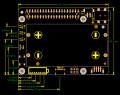
X728 V1.3 PCB Layout
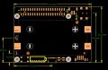
X728 V2.0 PCB Layout
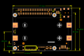
X728 V2.1 PCB Layout


18650 battery dimension
 Do not use 18650 battery with built-in protection circuit
Raspberry Pi Official GPIO Expansion describe

Installation Guide
Installation Video for X728+X728-A1+X728-A2: https://youtu.be/q_TmqMNhJPM

Return to X728
Enable comment auto-refresher
Anonymous user #53
Permalink |
Lisa
Anonymous user #52
Permalink |
Walker
Anonymous user #51
Permalink |
Walker
Anonymous user #50
Permalink |
Walker
Anonymous user #49
Permalink |
Walker
Anonymous user #48
Permalink |
Walker
Anonymous user #48
Walker
Anonymous user #47
Permalink |
Walker
Anonymous user #46
Permalink |
Anonymous user #44
Permalink |
Anonymous user #45
Harry
Anonymous user #44
Anonymous user #43
Permalink |
Lisa
Anonymous user #42
Permalink |
Lisa
Anonymous user #42
Permalink |
Lisa
Anonymous user #42
Lisa
Anonymous user #41
Permalink |
Lisa
Anonymous user #40
Permalink |
Lisa
Anonymous user #39
Permalink |
Lisa
Anonymous user #39
Lisa
Anonymous user #39
Anonymous user #38
Permalink |
Lisa
Anonymous user #37
Permalink |
Lisa
Anonymous user #36
Permalink |
Lisa
Anonymous user #35
Permalink |
Anonymous user #35
Lisa
Anonymous user #33
Permalink |
Lisa
Anonymous user #32
Permalink |
Lisa
Anonymous user #30
Permalink |
Lisa
Lisa
Anonymous user #31
Anonymous user #29
Permalink |
Lisa
Anonymous user #28
Permalink |
Lisa
Anonymous user #28
Permalink |
Lisa
Anonymous user #27
Permalink |
Lisa
Anonymous user #26
Permalink |
Harry
Anonymous user #25
Permalink |
Lisa
Anonymous user #24
Permalink |
Lisa
Anonymous user #24
Anonymous user #20
Permalink |
Lisa
Anonymous user #21
Lisa
Anonymous user #22
Lisa
Anonymous user #23
Anonymous user #22
Lisa
Anonymous user #19
Permalink |
Lisa
Anonymous user #18
Permalink |
Lisa
Anonymous user #17
Permalink |
Lisa
Anonymous user #14
Permalink |
Anonymous user #15
Anonymous user #16
Anonymous user #13
Permalink |
Anonymous user #12
Permalink |
Anonymous user #11
Permalink |
Anonymous user #5
Permalink |
Cindy
Anonymous user #10
Permalink |
Xiali
Anonymous user #9
Permalink |
Anonymous user #34
Lisa
Anonymous user #8
Permalink |
Xiali
Anonymous user #6
Permalink |
Anonymous user #7
Xiali
Anonymous user #7
Anonymous user #7
Anonymous user #5
Permalink |
Cindy
Anonymous user #5
Permalink |
Anonymous user #5
Permalink |
Anonymous user #4
Permalink |
Anonymous user #1
Permalink |
Anonymous user #2
Anonymous user #3