Sackable & universal UPS shiled, 12V & 5V dual output voltage for all SBC
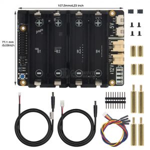
X-UPS V1.3 Accessories & Dimension
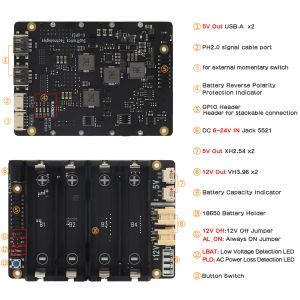
X-UPS1 V1.3 Interface Schematic
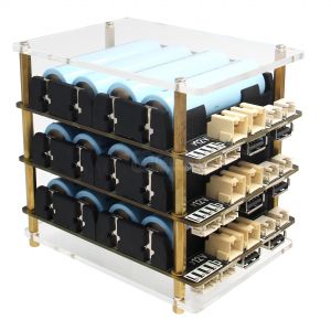
X-UPS1 UPS with Acrylic Plate
Overview
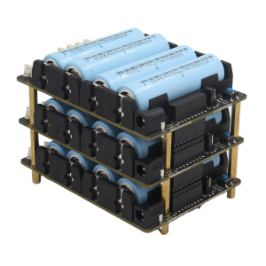
The X-UPS1 is an universal stackable uninterruptible power supply (UPS) shield for most Single-Board Computers (SBC) that uses 12Vdc or 5Vdc. The UPS ensures that in event of power interruption, a battery or any other power source will intervene without any effect on your board.
Our convenient stackable design allows you to connect several UPS modules on your boards to provide long-lasting & higher output power for even the most demanding SBC set ups that have constant power connections 24 hours a day, seven days a week.
Features
| For use with |
Most Single-Board Computers (SBC) that uses 12Vdc or 5Vdc,
- SBC Example: Orange Pi 5 / Jetson Nano / Raspberry Pi / Tinker Board / Arduino etc.
|
| Key Features |
UPS Output
- Provides dual 12Vdc & 5Vdc or single 5Vdc output
- Each board provides max 3A power backup
- Can be stacked to increase output current and battery life
- Total output current could be 3A multiplied by the No. of boards
- Reverse Current Protection
- Integrate Advanced Power MOSFET with Equivalent of 7mΩ RDS(ON) to reduce power loss
Battery Charging
- Supports 3000mA fast battery charging
- Battery over current protection and over voltage protection
- Protection of battery cell Reverse Connection
- Lowbattery detection (LED and 3.3V level output)
- Onboard 4 green LEDs indicate battery charging and discharging levels of 25%, 50% , 75% and 100%
- 18650 4cell lithium Ion holders
Power Input
- Integrated highefficiency stepdown DC/DC converter
- Wide 6V to 24V operating input range
- Up to 95% Efficiency
- Up to 10A output current to keep 3A fast charging and powering your SBC at the same time
- Allows powering from a car, a solder pannel and other power sources
- Most common power input jack: 5.5x2.1mm
Power Control
- Onboard push button to control power on /off (PressON, Hold the button pressed at least 3s OFF )
- Onboard LEDs shows the status of power output
- AC power loss or power adapter failure detection (LED and 3.3V level output)
- Jumper setting to enable Auto power on when power applied or restored
- Jumper setting to disable 12V output
- Ultralow standby power consumption to maximize battery life
- Advanced system powerpath management avoids batteries frequent charging and discharging
Misc
- Power output connectors : VH3.96 x2 (12V) / XH2.54 x2 (5V) / USB TypeA x2 (5V)
- PH2.0-4P for external power switch
- PH2.0-4P for low battery output and AC power loss deteciton
|
| Spec |
- Power input (Single board) : 6-24Vdc ±5%, ≥3A
- UPS output voltage : 12Vdc ±5%, 5.1Vdc ±5%
- UPS output current (Single boards) : Max 3A
- UPS output current (Stackable boards) : 3A x No. of the boards
- UPS charging current (Single board) : 2.3~3.2A
- Terminal Battery Voltage : 4.24V
- Battery Recharge Threshold : 4.1V
- Battery low detection: ≤3V
|
| Note |
Notes for stackable application:
- All power input are connected together via the 18-pin female header, input current is subject to the No. of boards.
- You can use one board to turn on/off all stackable boards. (be noted that which board you press the button to turn on, also must the same board to turn off.)
- If the jumper for auto power on is inserted on one board, then this funciton will be enabled for all stackable boards.
|
Packing List
- 1 x X-UPS1 Expansion Board
- 1 x VH3.96 to 12V DC5525
- 1 x XH2.54 to 5V DC5521
- 1 x GPIO Header
- 2 x Jumper link Pitch 2.54mm
- 4x Spacer F/F M2.5x10mm
- 4 x Spacer M/F M2.5x25+6mm
- 4 x Screw M2.5 x 5mm
User Manual
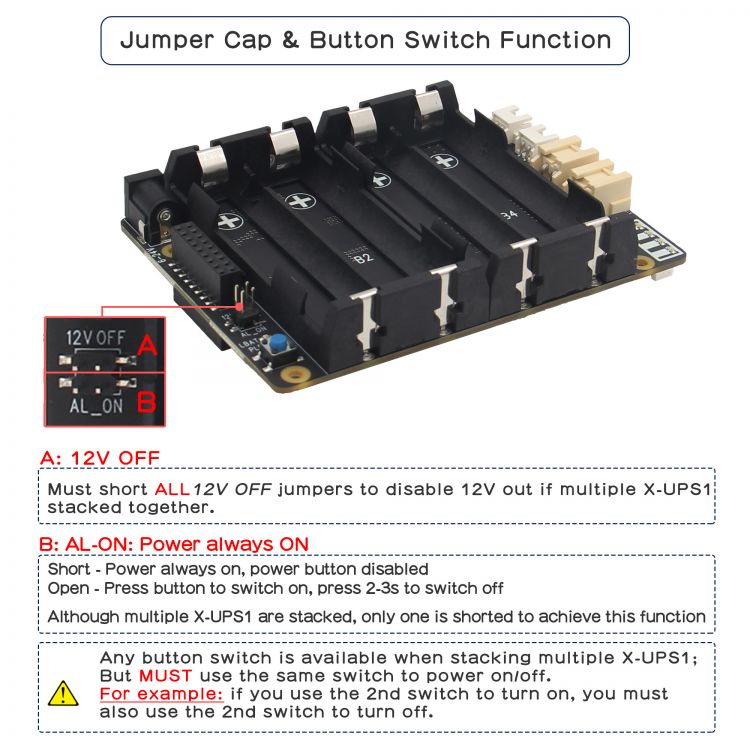
X-UPS1 V1.3 Jumper Cap & Button Switch Guidance:
PCB Dimension
X-UPS1 Dimensions source file (DXF): File:X-UPS1-PCB.dxf - You can view it with Autodesk Viewer online


Enable comment auto-refresher
Anonymous user #6
Permalink |
Lisa
Anonymous user #5
Permalink |
Anonymous user #4
Permalink |
Walker
Anonymous user #3
Permalink |
Walker
Walker
Anonymous user #3
Permalink |
Anonymous user #2
Permalink |
Walker
Anonymous user #1
Permalink |
Walker