LVDS2
Contents
Overview
Due to the wide variety of screens on the market, the EDID recognition of different screens may have compatibility issues, which may lead to incorrect screen colors or abnormal screens or no display.
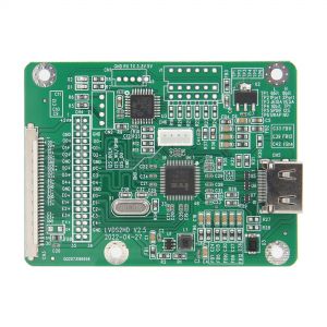
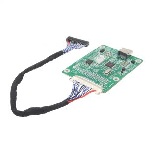
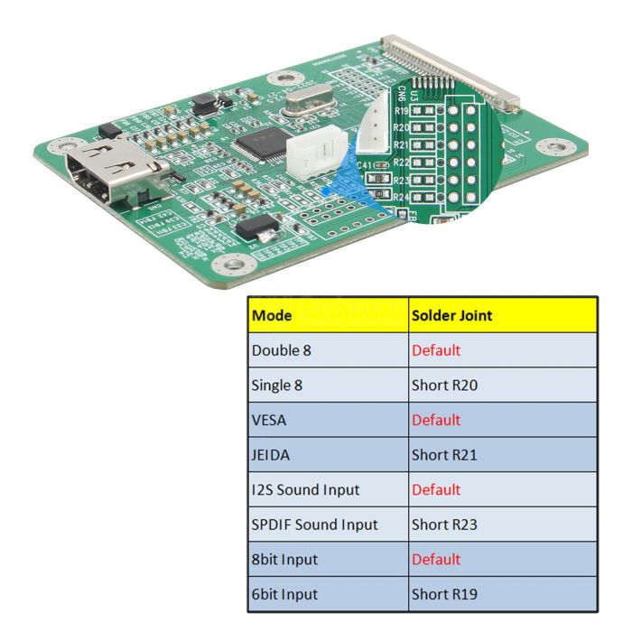
This LVDS2 board convert LVDS input signal to HDMI output, the resolution is VESA standard in default. If you need change to single 8 mode, please short the R20 on the LVDS2 board.
Because it is the DIY product, so sometimes there may be the compatibility problem. When it shows no signal or no sound, it may be the compability problem.
Features
- LVDS input signal to HDMI output, the maximum bandwidth can reach 150MHz;
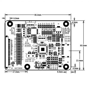
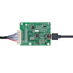
- LVDS input interface adopts the general 30-pin socket FI-X30SSLA-HF, which supports dual 8 inputs, and the riginal screen cable can be used directly;
- Double 8 mode in default
- I2S sound input in default
- VESA standard resolution in default
- 8bit in default
- Not only supports standard HDMI signals, but also supports other graphics format signals, the common formats are as follows: 1920x1200, 1920x1080, 1600x1200, 1280x1024, 1280x720, etc.
- Support LVDS signal to spread spectrum
- Powered by 5V in the screen cable
Packing List
- 1 x LVDS to HDMI Converter with Cable (cable length: 22cm)
User Manual
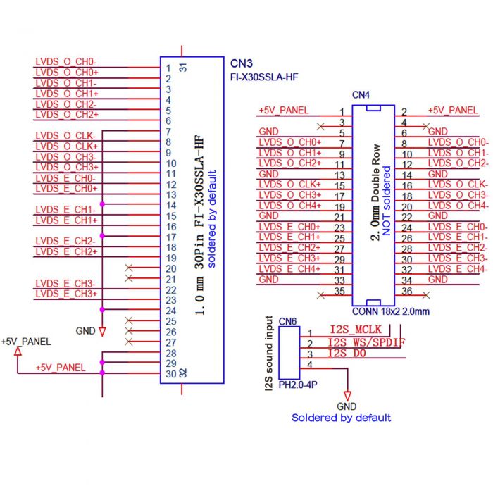
CN3/CN4/CN6 Interface Definition
How to Change the Mode
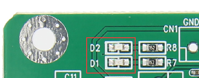
D1&D2 LED Indicator
After power on, D1 flashes,it indicates that the MCU is working normally. After receiving the LVDS signal, D2 is always on.
If D2 is not light on, it means that no LVDS signal is received, and the line sequence needs to be checked.
Enable comment auto-refresher
Anonymous user #14
Permalink |
Anonymous user #13
Permalink |
Anonymous user #12
Permalink |
Anonymous user #11
Permalink |
Lisa
Anonymous user #10
Permalink |
Walker
Anonymous user #9
Permalink |
Walker
Anonymous user #8
Permalink |
Walker
Anonymous user #7
Permalink |
Walker
Anonymous user #6
Permalink |
Walker
Anonymous user #5
Permalink |
Walker
Anonymous user #4
Permalink |
Anonymous user #3
Permalink |
Anonymous user #3
Permalink |
Anonymous user #2
Permalink |
Lisa
Anonymous user #1
Permalink |
Lisa