Open main menu

10.1 inch LCD for Tablet PC, raspberry pi

Contents

DESCRIPTION

LR1012K01 is a color active matrix TFT (Thin Film Transistor) liquid crystal display (LCD) that uses amorphous silicon TFT as switching devices. This model is composed of a TFT LCD panel, a driver circuit and a backlight unit. The resolution of a 10.1" contains 2560 x 1600 and can display up to 16,194,277 colors. 6 O'clockdirection is the optimum viewing angle.

FEATURES

- High contrast ratio, Ultra wide viewing angle

- WQ (2560 x 1600) resolution

- Low power consumption

- LED Back Light with internal LED Driver

- With OBD menu, support multi languge menu.

- eDP(V1.1) Input Interface

Power Supply

Wide voltage input, DC 7V-12V, Max. 2A

Application

- Raspberry Pi 3 Model B+\ 3B \ 2B \ B+

- Orange Pi Series

- Beaglebone Black Series

- Desktop Computer

- Tablet PC

Specification

- Display area: 216.576mm(H) X 135.36mm(V) (10.05”diagonal)

- Driver element: a-Si TFT active matrix

- Display colors: 16,194,277(6bit+FRC)

- Resolution: 2560 * 1600 (16:10)

- Pixel arrangement: RGBW vertical stripe

- Pixel pitch: 0.0423mm(H) x 0.0846mm(V) (TYP.)

- Display Mode: Normally black (PLS mode)

- Surface treatment: 2H (Glare)

Packing List

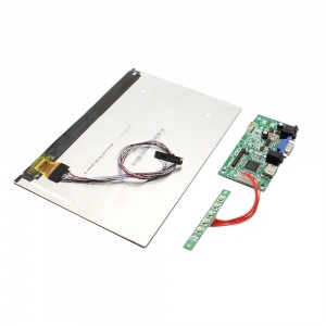
  • 1 x 10.1 Inch Full HD Screen
  • 1 x Drive Board
  • 1 x Keyboard Board

Document

File:LR1012K01-EDP.PDF

Add your comment
Geekworm Wiki welcomes all comments. If you do not want to be anonymous, register or log in. It is free.


Anonymous user #7

44 months ago
Score 0  
I want to send a backlight control signal with a Raspberry Pi to the M860A controller board. Is this feasible? If so are there any available resources on how this can be signaled?
 

Anonymous user #6

56 months ago
Score 0  

oops that did not work properly, let's try this:

PVCC 1 2 PVCC

GND 3 4 GND

TX0- 5 6 TX0+

TX1- 7 8 TX1+

TX2- 9 10 TX2+

TX3- 11 12 TX3+

AUX+ 13 14 AUX-

GND 15 16 DPHP

PWM 17 18 LEDEN

GND 19 20 12V

GND 21 22 12V

DPSCL 23 24 DPSDA

GND 25 26 nc

GND 27 28 GND

PVCC 29 30 PVCC
 

Anonymous user #5

58 months ago
Score 0  
Is it possible to get CORRECT pinout of the 30-pin connector from the screen?? There is a manual on the wiki, but it shows 45-pin connector. And when you try to match the wires to the labeled pins on the control board, the colors does not match. Red is connected to pin that is labeled GND, black is connected to PVCC etc. I am trying to use the screen with another LVDS board, but it is impossible to do so, without the pin specification.
 

Anonymous user #6

56 months ago
Score 0  

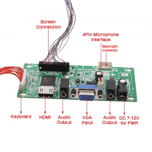
Pinout is on the back of the the PCB (pin 1 is the pin closest to the keyboard connector)

PVCC 1 2 PVCC GND 3 4 GND TX0- 5 6 TX0+ TX1- 7 8 TX1+ TX2- 9 10 TX2+ TX3- 11 12 TX3+ AUX+ 13 14 AUX- GND 15 16 DPHP PWM 17 18 LEDEN GND 19 20 12V GND 21 22 12V DPSCL 23 24 DPSDA GND 25 26 nc GND 27 28 GND

PVCC 29 30 PVCC
 

Anonymous user #4

60 months ago
Score 0  
How do i change language? It is in chineese!
 

Anonymous user #3

64 months ago
Score 0  

Hi, Can this screen be used as transparent matrix? For making 3d printer, to pass UV light?

Thank you
 

Anonymous user #2

65 months ago
Score 0  
Can this be used with a Smartphone that has hdmi output (like s Note 8)?
 

Anonymous user #1

72 months ago
Score 0  
What is the pin layout of the power socket?
 

Admin

72 months ago
Score 0  

Hello sir, Please refer to above Document: File:LR1012K01-EDP.PDF. Best regards,

Geekworm/Cindy