Difference between revisions of "X1300 Software"
| Line 1: | Line 1: | ||
{{GD Template Impl}} | {{GD Template Impl}} | ||
| − | This tutorial is only for [[X1300]] and [[X1301]] | + | This tutorial is only for [[X1300]] and [[X1301]] and [[X630]] |
This tutorial is mainly based on the tool '''v4l2-ctl''' tool and provides a simple example to check whether the x1300 is working properly on the Raspberry Pi 5. It is not only a tutorial, but also a basis for you to check whether the X1300 is damaged. Of course, you can also consider using other video tools such as '''GStreamer''' to get similar functions. | This tutorial is mainly based on the tool '''v4l2-ctl''' tool and provides a simple example to check whether the x1300 is working properly on the Raspberry Pi 5. It is not only a tutorial, but also a basis for you to check whether the X1300 is damaged. Of course, you can also consider using other video tools such as '''GStreamer''' to get similar functions. | ||
Revision as of 11:53, 16 December 2024
This tutorial is only for X1300 and X1301 and X630
This tutorial is mainly based on the tool v4l2-ctl tool and provides a simple example to check whether the x1300 is working properly on the Raspberry Pi 5. It is not only a tutorial, but also a basis for you to check whether the X1300 is damaged. Of course, you can also consider using other video tools such as GStreamer to get similar functions.
Before starting the following tutorial, you must also have completed the physical connection of X1300/X1301, and also ensure that there is HDMI signal transmitted to X1300/X1301
Now assumes you've already set up a Raspberry Pi with Raspbian12(bookworm). For help installing the Debian-based OS on your Pi, check out the docs on https://www.raspberrypi.com/
To check the kernel version, execute the following command: (OS kernel upgrades often bring about some uncertain issues)
uname -a
Maybe the result is following:
uname -a
Linux raspberrypi 6.6.31+rpt-rpi-v8 #1 SMP PREEMPT Debian 1:6.6.31-1+rpt1 (2024-05-29) aarch64 GNU/Linux
1. To enable the device tree overlay in the /boot/firmware/config.txt
sudo nano /boot/firmware/config.txt
Add two lines at the end of the file that reads like this:
dtoverlay=tc358743,4lane=1
dtoverlay=tc358743-audio
PS: If you use X630, please remove ,4lane=1 and dtoverlay=tc358743-audio
Press Ctrl + O & Enter to save
Press Ctrl + X to Exit
2. Reboot the Raspberry Pi 5 for the settings to take effect
sudo reboot
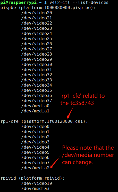
3. Check video devices list
v4l2-ctl --list-devices
4. Create an 1920*1080P EDID txt file to setup the HDMI to CSI adapter before you can connect it to a HDMI source. This EDID file will enable the video and audio mode supported.
sudo nano 1080P60EDID.txt
Copy below EDID data and paste to 1080P60EDID.txt, or download EDID data from https://github.com/6by9/CSI2_device_config/blob/master/1080P60EDID.txt
00ffffffffffff005262888800888888
1c150103800000780aEE91A3544C9926
0F505400000001010101010101010101
010101010101011d007251d01e206e28
5500c48e2100001e8c0ad08a20e02d10
103e9600138e2100001e000000fc0054
6f73686962612d4832430a20000000FD
003b3d0f2e0f1e0a202020202020014f
020322444f841303021211012021223c
3d3e101f2309070766030c00300080E3
007F8c0ad08a20e02d10103e9600c48e
210000188c0ad08a20e02d10103e9600
138e210000188c0aa01451f01600267c
4300138e210000980000000000000000
00000000000000000000000000000000
00000000000000000000000000000015
5. Loading the EDID data
v4l2-ctl -d /dev/v4l-subdev2 --set-edid=file=/home/pi/1080P60EDID.txt --fix-edid-checksums
PS:Pay attention to the directory of your edid file
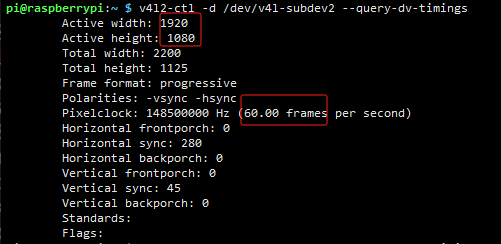
6. Query the current HDMI input signal source information. If the resolution shows 0, it means that no input source signal is detected. At this time, you need to check the hardware connection and then repeat the above steps to troubleshoot.
v4l2-ctl -d /dev/v4l-subdev2 --query-dv-timings
PS: Make sure to connect the HDMI source device to get the HDMI signal, if you can't get the correct resolution here, consider adjusting the resolution of your source device to match the EDID.
7. Applying the screen timing to the capture setup
v4l2-ctl -d /dev/v4l-subdev2 --set-dv-bt-timings query
8. Initialize/reset media
media-ctl -d /dev/media2 -r
Please note that the /dev/media number can change. Go to step 3 to check the media number. please change /dev/media2 to /dev/media1 if your media number is 1, and so on
9. Connect CSI2's pad4 to rp1-cfe-csi2_ch0's pad0.
media-ctl -d /dev/media2 -l ''\''csi2'\'':4 -> '\''rp1-cfe-csi2_ch0'\'':0 [1]'
10. Configure the media node.
media-ctl -d /dev/media2 -V ''\''csi2'\'':0 [fmt:RGB888_1X24/1920x1080 field:none colorspace:srgb]'
media-ctl -d /dev/media2 -V ''\''csi2'\'':4 [fmt:RGB888_1X24/1920x1080 field:none colorspace:srgb]'
media-ctl -d /dev/media2 -V ''\''tc358743 4-000f'\'':0 [fmt:RGB888_1X24/1920x1080 field:none colorspace:srgb]'
Please note that the /dev/media number can change. Go to step 3 to check the media number. please change /dev/media2 to /dev/media1 if your media number is 1, and so on
11. Set output formats
v4l2-ctl -v width=1920,height=1080,pixelformat=RGB3
12. Capture frames and save to /home/pi (filename: csitest.yuv)
v4l2-ctl --verbose -d /dev/video0 --set-fmt-video=width=1920,height=1080,pixelformat='RGB3' --stream-mmap=4 --stream-skip=3 --stream-count=2 --stream-to=csitest.yuv --stream-poll
13. To play the YUV file on Raspberry Pi OS desktop, use FFplay. (Run the following command on local terminal window, Not work if executing the command from SSH).
ffplay -f rawvideo -video_size 1920x1080 -pixel_format bgr24 csitest.yuv


Enable comment auto-refresher
Anonymous user #17
Permalink |
Ruby
Ruby
Anonymous user #16
Permalink |
Anonymous user #15
Permalink |
Lisa
Anonymous user #14
Permalink |
Anonymous user #13
Permalink |
Anonymous user #12
Permalink |
Anonymous user #11
Permalink |
Anonymous user #10
Permalink |
Anonymous user #9
Permalink |
Anonymous user #8
Permalink |
Lisa
Anonymous user #7
Permalink |
Harry
Anonymous user #5
Permalink |
Anonymous user #6
Anonymous user #4
Permalink |
Lisa
Anonymous user #3
Permalink |
Lisa
Anonymous user #1
Permalink |
Anonymous user #2