DIDO
Contents
Instruction
NOTE:
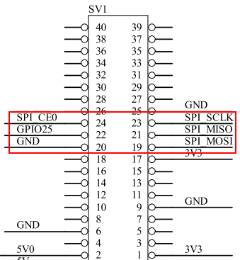
This DIDO module supports also Raspberry Pi 5 hardware, but need to change the gpio no, refer to #FAQ Q3
The DIDO is upgraded to Version 1.3, and it's support the raspberry pi 4 model B now. We have only reduced the PCB size, nothing else has changed.
How to use the DIDO on Raspberry PI 4B Please refer to File:How to use the DIDO on Raspberry PI 4B-EN.pdf
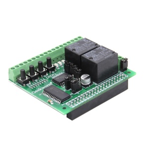
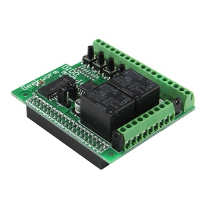
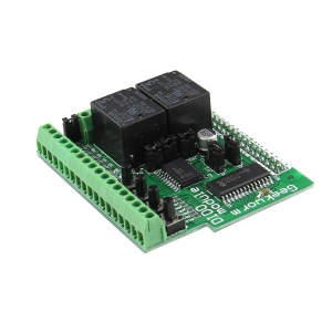
DIDO module includes components like relays,switches, digital and analog I/O that will allow for connection to sensors ,motors, lights, etc. and be controlled by the Raspberry Pi board.
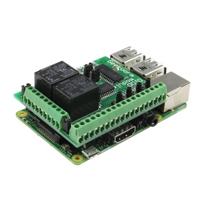
The digital DIDO module interface board fits the original Raspberry Pi models A and B. DIDO module has been redesigned to fit the Raspberry Pi models A and B.
Product highlights
Typical applications:
- Education
- Home/Industrial automation
- Security monitoring
- Internet of Things gateway
- Remote monitoring
- Hobbyist projects and games
- I/O expander
- User interface for systems
Features:
- 2 Change Over Relays
- 4 Tactile Switches
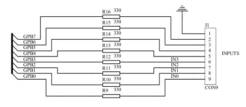
- 8 Digital Inputs、touch sensitive inputs
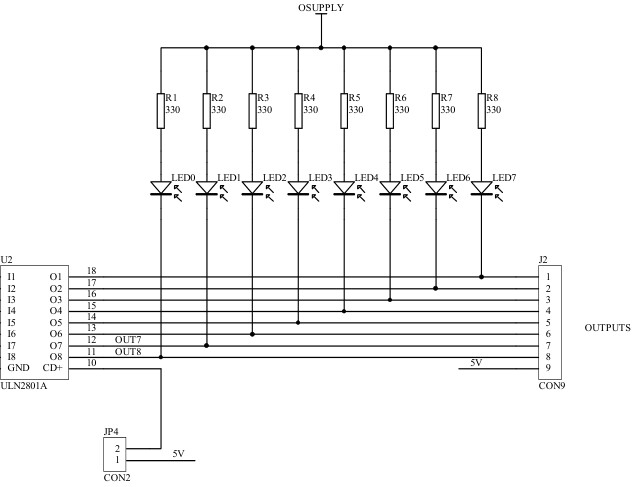
- 8 Open-Collector Outputs
- 8 LED Indicators
- Graphical Emulator
- Easy to program in Python 3 and 2, Scratch and C
- Graphical emulator
Technical specifications:
- Changeover relays, 20V 5A switching max
- 1.5mm screw terminal hole size
- Operating Temp -40° to 85°
Fitting instructions
Warnings
- Ensure that no power is supplied to Raspberry Pi, or DIDO boards
when plugging or unplugging. DIDO sits neatly above the Raspberry Pi and connects using the expansion connector. Take care to ensure all expansion pins are lined up with the holes on the DIDO socket. Check the alignment for left and right, and front and back before pushing down and never force the boards together if they don’t slide smoothly.
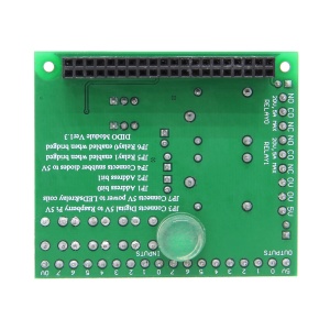
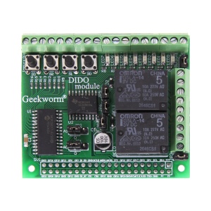
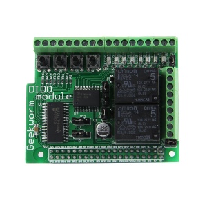
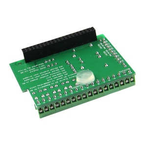
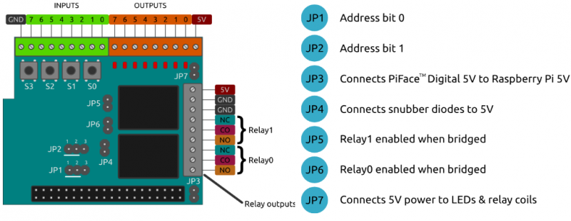
Tour of hardware
Detail refer to File:DIDO-Piface2-Getting-starte.pdf
Document & Download
- File:How to use the DIDO on Raspberry PI 4B-EN.pdf
- File:How to use the DIDO on Raspberry PI 4B-CN.pdf
- File:Software-package.zip
- File:DIDO-module-Overview.pdf
- File:Install-DIDO-module-Software.pdf
- File:DIDO-Piface2-Getting-starte.pdf
- Test sample: File:Simple led.zip
- File:Draw Marquee-LED Banner about DIDO module(1).pdf
- For step by step help and ideas for projects visit: Piface Guide
Application
- File:Controlling a remote control with the piface digital.pdf
- File:Simple web control with PiFace Digital.pdf
test source code
#!/usr/bin/python3

from time import sleep
import pifacedigitalio

DELAY = 0.1   # seconds

if __name__ == "__main__":
   pifacedigital = pifacedigitalio.PiFaceDigital()
   while True:
       sleep(DELAY)
       pifacedigital.output_port.value=pifacedigital.input_port.value
FAQ
Q1: Can't install PiFace Digital software
A: Please refer to the Raspberry_Pi_DIDO_Board#Document_.26_Download to install manually.
(https://www.raspberrypi.org/forums/viewtopic.php?t=194332 for reference)
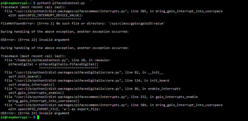
Q3: How to get DIDO working on Raspberry Pi 5
A: When use it on the Raspberry Pi 5, You may encounter the following errors:
Need to run the command:
sudo nano /usr/lib/python3/dist-packages/pifacecommon/interrupts.py
Then search the GPIO_INTERRUPT_PIN = 25 line and change 25 to 596
PS: Run 'cat /sys/kernel/debug/gpio' to get new gpio no on raspberry pi 5
Enable comment auto-refresher
Anonymous user #1
Permalink |
Danperryy
Permalink |
Harry