Power Pack Pro
Contents
Overview
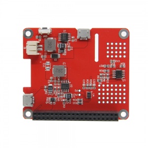
This is a power expansion Board especially designed for Raspberry Pi, which enables to use the Raspberry Pi with a moveable power source. It's more convenient to use external 3.7V Lithium battery or 3.7V 18650 Lithium battery;
Specifacation
Features
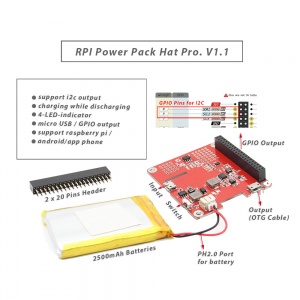
- Supports I2C Output with Capacity & Voltage Reading Function
- Supports Raspberry pi or Android & Apple Phone or Pad or other electronic device charging;
- Supports charging while discharging,(Very stable, the maximum output current can up to 1.8A while charging, but the chip heat will become larger. maybe you can place a external heatsilk on clip.)
- With 4 LED power indicator;
- Standard dimension of Raspberry Pi HAT;
- Two power supply modes: GPIO power output and Micro USB power out (you can use OTG cable to connect it);
- Removable battery, The external lithium battery requirements: 3.7V lithium battery;
- Built-in power path management, perfect support charging While discharging.
- Intelligent 3-stage charging (trickle, constant current, constant voltage), it can effectively extend the battery life.
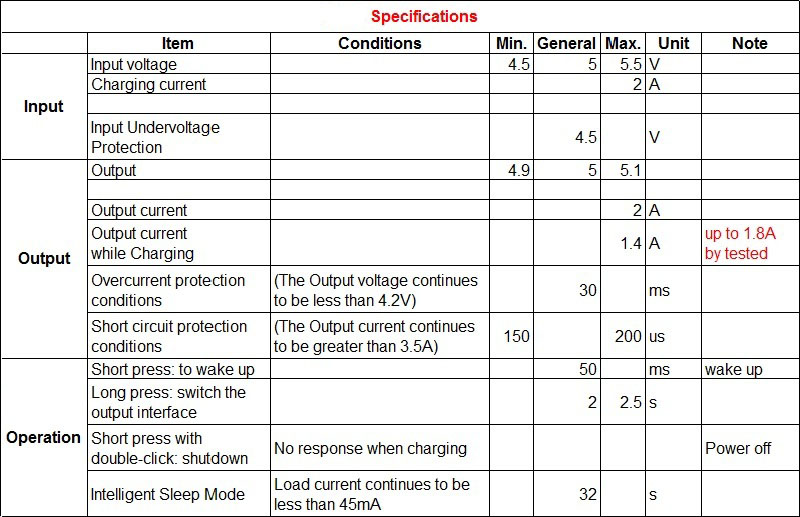
- Maximum discharge current: 2A, Maximum charge current: 1.8A;
- Output protection: over current, short circuit, under voltage protection;
- Input protection: over voltage, overcharge, under voltage protection;
Check I2C on Rasbperry pi
check if there is a I2C device;
sudo i2cdetect -y 1
i2cdump -y 1 0x62
0x62 is device address. You can see:0x0A address register default value is 0xC0
i2cset -y 1 0x62 0x0A 0x00
Wake-up the device I2C function; MODE register address 0x0A set to 0x00
i2cdump -y 1 0x62;
VCELL(cell voltage) address:0x02 - 0x03
PS: 0x62 is the device address of I2C device(CW2015 power monitoring chip)
How to read the voltage values that saved by chip register?
sudo i2cget -y 1 0x62 0x02 w
get the value 0xf82f; swap high and low byte to get 0x2ff8;
0x2ff8 converted to decimal number is 12280;
12280 * 305 = 3745400 uV
3745400/1000000 = 3.7454V
PS: 305 is a fixed value (Fix factor value);
How to read the remaining capacity (percentage) estimated by the chip?
1. Read the integer part of the battery percentage;
sudo i2cget -y 1 0x62 0x4 b
the resulting value is 0x11;
Converted to 10 decimalism is 17, then the remaining capacity is 17%;
2. Read the fractional part of the battery percentage
sudo i2cget -y 1 0x62 0x5 b
the resulting value is 0x95;
Converted to decimalism is 149;
Then the fractional part is 149/256 = 0.58;
So the chip estimated remaining capacity (percentage) is 17.58%.


Enable comment auto-refresher
Anonymous user #2
Permalink |
Szymon
Permalink |
Anonymous user #1