ESP32-WROVER Module
Contents
About ESP32-WROVER Module
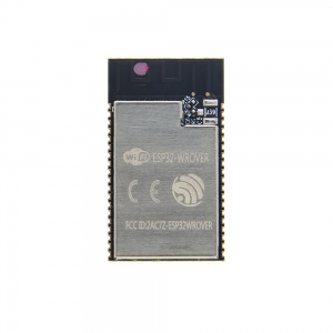
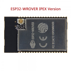
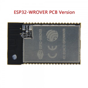
- ESP32-WROVER is a powerful, generic WiFi-BT-BLE MCU module that targets a wide variety of applications,ranging from low-power sensor networks to the most demanding tasks, such as voice encoding, music streamingand MP3 decoding. The ESP32-WROVER has two versions: The ESP32-WROVER IPEX Module uses an IPEX antenna while the ESP32-WROVER PCB module has a PCB antenna.
Updated New Version ESP32-WROVER-B Module
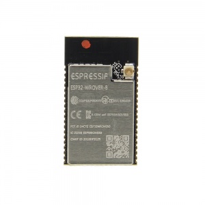
- ESP32-WROVER-B is a powerful, generic WiFi-BT-BLE MCU module that targets a wide variety of applications, ranging from low-power sensor networks to the most demanding tasks, such as voice encoding, music streaming and MP3 decoding.It features a 4 MB external SPI flash and an additional 8 MB SPI Pseudo static RAM (PSRAM).
Overviews
- ESP32-WROVER is a powerful, generic WiFi-BT-BLE MCU module that targets a wide variety of applications,ranging from low-power sensor networks to the most demanding tasks, such as voice encoding, music streamingand MP3 decoding.
- At the core of this module is the ESP32-D0WDQ6 chip*, same as ESP-WROOM-32 module. Compared to ESPWROOM-32,ESP32-WROVER has an additional SPI Pseudo static RAM (PSRAM) of 32 Mbits. As such, ESP32-WROVER features both 4 MB external SPI flash and 4 MB external PSRAM.
- The ESP32-WROVER module has a PCB antenna, while the ESP32-WROVER-I uses an IPEX antenna. The information in this datasheet is applicable to both of the two modules.
- The chip embedded is designed to be scalable and adaptive. There are two CPU cores that can be individually controlled, and the clock frequency is adjustable from 80 MHz to 240 MHz. The user may also power off the CPU and make use of the low-power co-processor to constantly monitor the peripherals for changes or crossing of thresholds. ESP32 integrates a rich set of peripherals, ranging from capacitive touch sensors, Hall sensors, low-noise sense amplifiers, SD card interface, Ethernet, high-speed SPI, UART, I2S and I2C.
- The integration of Bluetooth, Bluetooth LE and Wi-Fi ensures that a wide range of applications can be targeted,and that the module is future proof: using Wi-Fi allows a large physical range and direct connection to the internet through a Wi-Fi router, while using Bluetooth allows the user to conveniently connect to the phone or broadcast low energy beacons for its detection.
- The sleep current of the ESP32 chip is less than 5 µA, making it suitable for battery powered and wearable electronics applications. ESP32 supports a data rate of up to 150 Mbps, and 20.5 dBm output power at the antenna to ensure the widest physical range. As such the chip does offer industry-leading specifications and the best performance for electronic integration, range, power consumption,and connectivity.
- The operating system chosen for ESP32 is freeRTOS with LwIP; TLS 1.2 with hardware acceleration is built in as well. Secure (encrypted) over the air (OTA) upgrade is also supported, so that developers can continually upgrade their products even after their release.
Features
This chapter describes the modules and functions integrated in ESP32-WROVER.
- [CPU and Internal Memory]
ESP32-D0WDQ6 contains two low-power Xtensa® 32-bit LX6 microprocessors. The internal memory includes:
448 KB of ROM for booting and core functions.
520 KB (8 KB RTC FAST Memory included) of on-chip SRAM for data and instruction.
8 KB of SRAM in RTC, which is called RTC FAST Memory and can be used for data storage; it isaccessed by the main CPU during RTC Boot from the Deep-sleep mode.
8 KB of SRAM in RTC, which is called RTC SLOW Memory and can be accessed by the co-processor duringthe Deep-sleep mode.
1 kbit of eFuse, of which 256 bits are used for the system (MAC address and chip configuration) and theremaining 768 bits are reserved for customer applications, including Flash-Encryption and Chip-ID.
- [External Flash and SRAM]
ESP32 supports up to four 16-MB of external QSPI flash and SRAM with hardware encryption based on AES toprotect developers’ programs and data.
ESP32 can access the external QSPI flash and SRAM through high-speed caches.
Up to 16 MB of external flash are memory-mapped onto the CPU code space, supporting 8, 16 and 32-bitaccess. Code execution is supported.
Up to 8 MB of external flash/SRAM are memory-mapped onto the CPU data space, supporting 8, 16 and32-bit access. Data-read is supported on the flash and SRAM. Data-write is supported on the SRAM.
ESP32-WROVER integrates 4 MB of external SPI flash. The 4-MB SPI flash can be memory-mapped onto theCPU code space, supporting 8, 16 and 32-bit access. Code execution is supported.
In addition to the 4 MB SPI flash, ESP32-WROVER also integrates 4 MB PSRAM for more memory space.
- [Crystal Oscillators]
The ESP32 Wi-Fi/BT firmware can only support 40 MHz crystal oscillator for now.
- [RTC and Low-Power Management]
With the use of advanced power management technologies, ESP32 can switch between different power modes(see Table as below).
[Power modes]
Active mode: The chip radio is powered on. The chip can receive, transmit, or listen.
Modem-sleep mode: The CPU is operational and the clock is configurable. The Wi-Fi/Bluetooth basebandand radio are disabled.
Light-sleep mode: The CPU is paused. The RTC memory and RTC peripherals, as well as the ULPco-processor are running. Any wake-up events (MAC, host, RTC timer, or external interrupts) will wake up the chip.
Deep-sleep mode: Only the RTC memory and RTC peripherals are powered on. Wi-Fi and Bluetooth connection data are stored in the RTC memory. The ULP co-processor can work.
Hibernation mode: The internal 8-MHz oscillator and ULP co-processor are disabled. The RTC recoverymemory is powered down. Only one RTC timer on the slow clock and some RTC GPIOs are active. The RTC timer or the RTC GPIOs can wake up the chip from the Hibernation mode.
[Sleep Patterns]
Association sleep pattern: The power mode switches between the Active mode, Modem- and Lightsleep mode during this sleep pattern. The CPU, Wi-Fi, Bluetooth, and radio are woken up at predetermined intervals to keep Wi-Fi/BT connections alive.
ULP sensor-monitored pattern: The main CPU is in the Deep-sleep mode. The ULP co-processor takes sensor measurements and wakes up the main system, based on the data collected from sensors.
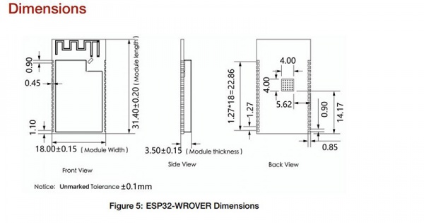
Size
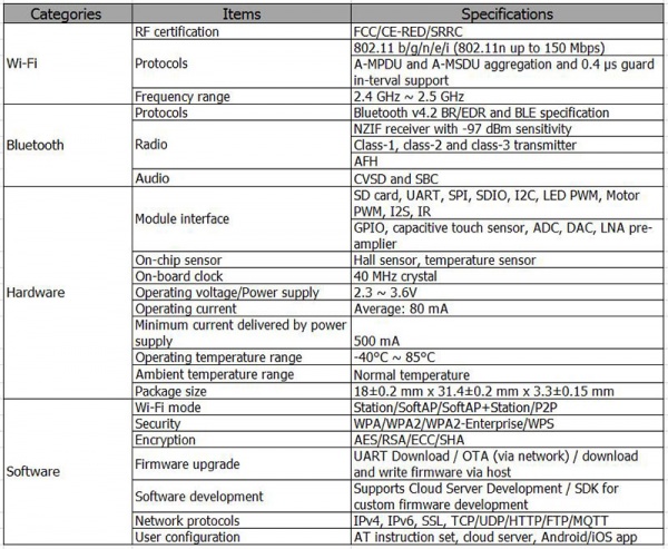
Specification
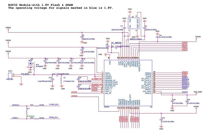
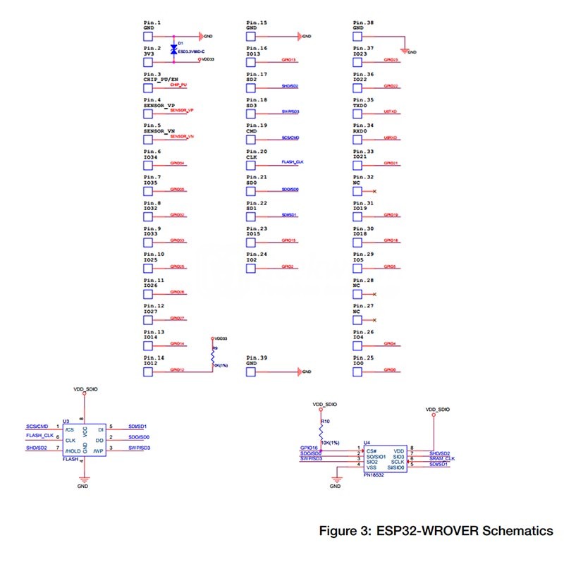
Schematics
Manual & FAQ
- Datasheet: ESP32-WROVER & ESP32-WROVER-I Datasheet
- Official Online: official site

Enable comment auto-refresher
Anonymous user #1
Permalink |