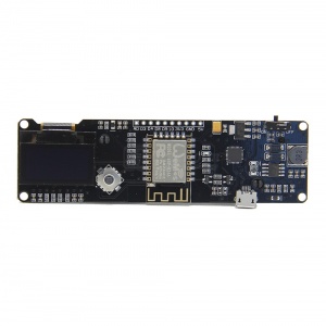
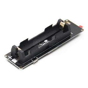
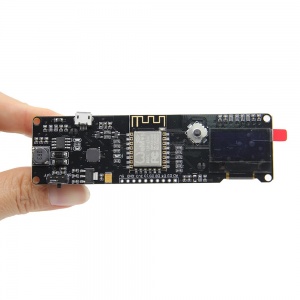
WEMOS ESP8266 Board with OLED & 18650 Battery Holder

From Geekworm Wiki
Revision as of 16:21, 1 September 2018 by Admin (talk | contribs)
(diff) ← Older revision | Latest revision (diff) | Newer revision → (diff)
Jump to navigation Jump to search

ESP32 Board with OLED

Features

  • One AD inputs.
  • Micro USB inputs.
  • One programmable LED (D0).
  • Integrated 18650 battery charging and discharging system.
  • One switch controls whether the 18650 battery is powered or not.
  • OLED's SDA and SCL connect to the D1 pin and the D2 pin respectively.
  • The five buttons are controlled by FLATH, RSET, D5, D6, and D7 respectively.
  • The 5 Digital pins can configure the write/read/interrupt/pwm/I2C/one-wire supported separately.
  • Operation and NodeMCU consistent, adding a programmable LED, you can use GPIO16 to control, display 8266 running status and other functions. Integrated OLED and five button, more convenient for development.
  • The design concept originates from the open source project NodeMCU, and the development board integrates 18650 charging and discharging systems with charging and discharging protection. At the same time, a OLED and five directional buttons are integrated to facilitate the development.


Specification

  • Charging Protection:Yes
  • Discharge Protection:Yes
  • Compatible With Arduino
  • Compatible With NodeMCU
  • Wide Voltage Input Range: 5V~12V
  • Charge Current:500 mA
  • Size(L*W*H):102 x 30 x 20 mm
  • Display Size: 0.96 Inch

ESP8266+18650+OLED-4.jpg

ESP8266+18650+OLED-5.jpg

Documents

Add your comment
Geekworm Wiki welcomes all comments. If you do not want to be anonymous, register or log in. It is free.


Anonymous user #4

11 months ago
Score 0++
I have also come across one of these and want to get the display working. Is there a github repo showing an example of the display code that works?

Anonymous user #4

11 months ago
Score 0++

Ok, I figured it out.


Get library + example file


Arduino IDE >> Tools >> Library Manager >> SSD1306 >> Install

Arduino IDE >> File >> Examples >> Adafruit SSD1306 >> ssd1306_128x64_i2c


alter definitions:


// on this board the address is not 0xDC, it is 0x3C

  1. define SCREEN_ADDRESS 0x3C

alter setup function:


void setup() { // // EXISTING_CODE // Serial.begin(9600); // // NEW_CODE // // Wire.h defaults are: SDA: 4, SCL: 5 // but we must reverse it for this board: // pin 5 SDA (this board) // pin 4 SCL (this board)

Wire.begin(5, 4);

Walker

11 months ago
Score 0++
Hello, this product has been out of stock for a long time, can you provide us with your order number?

Anonymous user #3

14 months ago
Score 0++
Picture labels misleading, or is there a ESP32 also with identically looking picture as the ESP8266?

Walker

14 months ago
Score 0++
Hello, we have not sold this product a long time ago, when did you buy it? Can you provide your order number?

Anonymous user #1

32 months ago
Score 0++
It would be very helpful to know what the model of the display is. I have been trying to set up one of these in ESPHome using the ssd1306 module but it's not working. I'm not sure if that is what this is using.

Anonymous user #2

31 months ago
Score 0++

Change pins SSD1306Wire display(0x3c, SDA, SCL); to SSD1306Wire display(0x3c, SCL, SDA); That board have some mistakes.

For example: if You move joystick Right it will Reset. 8-)