Difference between revisions of "G470"
| Line 3: | Line 3: | ||
==Overview== | ==Overview== | ||
| + | This G470 screw terminal expansion version expanded for the pins of the Raspberry Pi, which is compatible with Raspberry Pi 4B/3B+/3B/2B/B+/Pi Zero/Pi Zero W/Pi Zero 2 W. | ||
| + | It is convenient for user to connect and test GPIO when doing electronic experiments. There is the pin out information of the GPIO pin on the top of the terminal and on the side. | ||
==Features== | ==Features== | ||
Revision as of 12:20, 31 October 2024
Overview
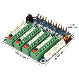
This G470 screw terminal expansion version expanded for the pins of the Raspberry Pi, which is compatible with Raspberry Pi 4B/3B+/3B/2B/B+/Pi Zero/Pi Zero W/Pi Zero 2 W. It is convenient for user to connect and test GPIO when doing electronic experiments. There is the pin out information of the GPIO pin on the top of the terminal and on the side.
Features
- Model: G470
- Compatible with Raspberry Pi 4B / Pi 3B+ / Pi 3B / Pi Zero
- Based on Raspberry Pi 40pin design, suitable for beginners of Raspberry Pi
- Lead out all GPIO function pins, easy and convenient access to the Raspberry Pi GPIO
- On-board ADDA chip, can read AD signals, output DA signals
- LED shows the status information of GPIO Pins. When the GPIO pin is operated and effective in the terminal, the LED matrix on the right side of the terminal will display the status of the GPIO pin
- On-board industrial terminal block female port, terminal with interface definition sticker. More beautiful and practical
Packing List
- 1 x Screw Terminal Block Breakout Board (Model: G470),
- 1 x Screws Pack
User Manual
PCF8591
Test image version: 2022-04-04-raspios-bullseye-armhf.img Raspberry pi 4B
Enable I2C
sudo nano /boot/config.txt
Ensure that I2C is on, and then restart the system.
sudo reboot
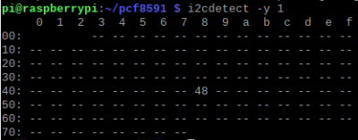
After restart, address 48 can be detected by I2C address detection command.
i2cdetect -y 1
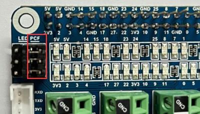
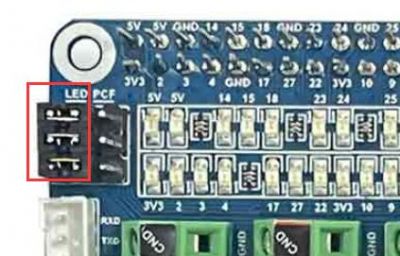
Ensure that jumper caps are connected to PCF.
Download sample codepcf8591
run command
cd pcf8591/
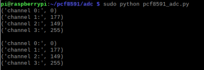
sudo python pcf8591_adc.py
Phenomenon:
4-channel print AD value
DAC
run command
sudo python pcf8591_dac.py
Phenomenon:
The LED lamp changes with the output value of DAC, and the brightness changes.
LED
Make sure that the jumper caps are connected to the LED.
Download GPIO_Test.py to raspberry pi.
run command
sudo python GPIO_Test.py
Phenomenon:
The power indicator LED is always on, and the GPIO connection LED is turned on in turn, and then turned off in turn, continuously circulating
FAQ
Q1: Question 1
A: Place the answer here.


Enable comment auto-refresher